Product Description
Product Description
Company Profile
FAQ
| Q:How to choose a multi-degree-of-freedom motion platform? A: First, clarify the type of platform needed (degrees of freedom, simulation platform, positioning platform, swing platform, vibration platform, etc.). Next, determine the platform’s payload, followed by size requirements, and finally, specify the platform’s attitude data. Q:What is the repeatability of a multi-degree-of-freedom motion platform? Q:What is the resolution of a multi-degree-of-freedom motion platform? Q:Does a multi-degree-of-freedom motion platform require maintenance? How to maintain it? Q:What is the maximum effective load that a multi-degree-of-freedom motion platform can handle? Q:What is the maximum angular position that a multi-degree-of-freedom motion platform can achieve? |
/* January 22, 2571 19:08:37 */!function(){function s(e,r){var a,o={};try{e&&e.split(“,”).forEach(function(e,t){e&&(a=e.match(/(.*?):(.*)$/))&&1
| Application: | Industrial |
|---|---|
| Speed: | High Speed |
| Number of Stator: | Single-Phase |
| Function: | Driving, Control |
| Certification: | ISO9001 |
| Motor: | Servo Motor |
| Customization: |
Available
|
|
|---|

How does the choice of pitch drives affect the overall performance and reliability of adjustable systems?
The choice of pitch drives has a significant impact on the overall performance and reliability of adjustable systems. Here’s a detailed explanation of how the choice of pitch drives affects these aspects:
- Performance:
The performance of adjustable systems, such as wind turbines or rotor blades, depends on the effectiveness and responsiveness of the pitch control mechanism. The choice of pitch drives directly influences the system’s ability to adjust the pitch angles accurately, quickly, and precisely. Several factors contribute to the performance impact:
- Speed and Responsiveness: The speed at which pitch drives can adjust the pitch angles affects the system’s ability to optimize performance in changing wind conditions. High-performance pitch drives with fast response times enable quicker and more precise adjustments, allowing the system to capture more energy from the wind and maintain optimal operating conditions.
- Control Accuracy: The accuracy of pitch angle control is crucial for maintaining the desired power output, load distribution, and overall system stability. The choice of pitch drives with precise control mechanisms ensures that the adjustable components accurately follow the control commands, minimizing deviations from the desired pitch angles and maximizing energy capture.
- Dynamic Performance: Adjustable systems often experience dynamic loads and varying wind conditions. The choice of pitch drives with robust dynamic performance characteristics, such as high torque capacity and low inertia, allows the system to effectively respond to dynamic loads, maintain stability, and optimize power generation.
- Reliability:
The reliability of adjustable systems is heavily influenced by the choice of pitch drives. The reliability aspect encompasses the system’s ability to operate consistently, withstand environmental conditions, and minimize the risk of failures or malfunctions. The choice of pitch drives impacts reliability in the following ways:
- Durability and Longevity: High-quality pitch drives designed for industrial applications provide durability and extended service life. They can withstand the operational stresses, environmental conditions, and mechanical loads associated with adjustable systems, reducing the likelihood of premature failures and the need for frequent replacements.
- Mechanical Integrity: The mechanical integrity of pitch drives, including the gears, bearings, and other moving components, is crucial for reliable operation. Choosing pitch drives from reputable manufacturers with a track record of reliable products ensures the use of robust and well-engineered components that can withstand continuous operation and minimize the risk of mechanical failures.
- Maintenance and Serviceability: The choice of pitch drives can influence the ease of maintenance and serviceability of adjustable systems. Well-designed pitch drives with accessible maintenance points, clear documentation, and available spare parts facilitate routine maintenance tasks, inspections, and repairs, reducing downtime and enhancing overall system reliability.
- Environmental Considerations: Adjustable systems often operate in challenging environmental conditions, such as high winds, temperature variations, and exposure to dust, moisture, or corrosive elements. The choice of pitch drives that are specifically designed and tested for such environments ensures resistance to environmental stresses, enhancing the reliability and longevity of the system.
In summary, the choice of pitch drives significantly affects the performance and reliability of adjustable systems. The selection of pitch drives with high-speed responsiveness, precise control accuracy, and robust dynamic performance optimizes the system’s performance in varying wind conditions. Additionally, choosing pitch drives with durability, mechanical integrity, ease of maintenance, and environmental suitability enhances the overall reliability of the system by minimizing the risk of failures, extending service life, and facilitating maintenance activities.

How do pitch drives contribute to precise and controlled pitch adjustments in machinery?
Pitch drives play a crucial role in achieving precise and controlled pitch adjustments in machinery. They provide the necessary actuation and control mechanisms to alter the pitch angle of rotating components, such as blades or propellers, with accuracy and reliability. Here’s a detailed explanation of how pitch drives contribute to precise and controlled pitch adjustments:
Pitch drives utilize various mechanisms, such as hydraulic, pneumatic, electric, or mechanical systems, to generate the required force or torque for pitch angle adjustments. These mechanisms are controlled through integrated control systems or external control signals, allowing for precise and controlled manipulation of the pitch angle. Here are the key ways in which pitch drives contribute to precise and controlled pitch adjustments:
- Accurate Positioning: Pitch drives offer the ability to accurately position the rotating components at the desired pitch angle. They allow for fine adjustments, enabling precise control over the orientation and alignment of the blades or propellers. This accuracy is essential in applications where optimal performance, efficiency, and aerodynamic characteristics are critical.
- Dynamic Control: Pitch drives enable dynamic control over the pitch angle, allowing for real-time adjustments based on changing conditions or operational requirements. With fast response times and precise control algorithms, pitch drives can adapt to varying loads, wind speeds, or other external factors, ensuring that the pitch angle is continuously optimized for optimal performance and safety.
- Load Distribution: In multi-blade systems, such as wind turbines or helicopter rotors, pitch drives contribute to precise and controlled pitch adjustments, resulting in optimized load distribution across the blades. By individually adjusting the pitch angle of each blade, pitch drives can distribute the load evenly, minimize aerodynamic imbalances, and enhance the overall efficiency and lifespan of the machinery.
- Safety and Protection: Pitch drives provide a means for safety and protection in machinery. They enable the adjustment of pitch angles to regulate the rotational speed, prevent over-speeding, and mitigate the effects of excessive loads or adverse operating conditions. By allowing controlled pitch adjustments, pitch drives contribute to safe and reliable operation, protecting the machinery from potential damage or catastrophic failures.
- Automation and Control Integration: Pitch drives can be integrated into automated control systems, allowing for seamless integration and coordination with other components or subsystems of the machinery. Through sensors, feedback loops, and control algorithms, pitch drives can be part of a closed-loop control system that continuously monitors and adjusts the pitch angle based on predefined parameters or operational objectives. This integration enhances the precision, responsiveness, and overall performance of pitch adjustments.
- Flexibility and Adaptability: Different types of pitch drives offer varying degrees of flexibility and adaptability. Electric pitch drives, for example, can offer programmable control algorithms, allowing for customized pitch adjustment profiles or adaptive control strategies. This flexibility enables the pitch drives to adapt to specific operating conditions, load variations, or performance requirements, ensuring precise and controlled pitch adjustments in diverse machinery applications.
Overall, pitch drives provide the necessary actuation and control mechanisms to achieve precise and controlled pitch adjustments in machinery. Through accurate positioning, dynamic control, load distribution, safety features, automation, and adaptability, pitch drives contribute to optimized performance, efficiency, and reliability in various industrial sectors.

Can you explain the primary functions and roles of pitch drives in specific applications?
Pitch drives play crucial roles in specific applications where precise control over the pitch angle of rotating components is required. The primary functions and roles of pitch drives vary depending on the application context. Here’s a detailed explanation of their primary functions and roles in specific applications:
In specific applications, pitch drives serve the following functions:
- Aircraft Propellers: In aircraft propellers, pitch drives are primarily responsible for adjusting the pitch angle of the propeller blades. The main function is to control the thrust generated by the propeller. By changing the pitch angle, the propeller can adapt to different flight conditions, such as takeoff, climb, cruise, or descent. The pitch drive allows pilots or automated control systems to optimize the propeller’s performance and efficiency based on the aircraft’s speed, altitude, and desired thrust.
- Wind Turbines: Pitch drives are essential components in wind turbines as they control the pitch angle of the turbine blades. The primary function is to regulate the aerodynamic performance of the blades to capture maximum wind energy. By adjusting the pitch angle, wind turbines can optimize power generation in varying wind conditions. The pitch drive system enables individual or collective blade pitch adjustment, ensuring efficient operation and protection against excessive wind speeds or storms.
- Marine Propulsion Systems: Pitch drives play a significant role in marine propulsion systems, such as ship propellers or watercraft thrusters. The primary function is to control the pitch angle of the propeller blades to optimize thrust and maneuverability. By adjusting the pitch angle, marine vessels can adapt to different operating conditions, including speed, load, and maneuvering requirements. Pitch drives enable dynamic control of the propeller pitch angle, allowing vessels to achieve efficient propulsion and precise maneuvering capabilities.
- Industrial Machinery: In industrial machinery applications, pitch drives are employed to control the pitch angle of rotating components like fan blades, impellers, or mixing blades. The primary function is to optimize the performance, efficiency, and flow characteristics of the machinery. By adjusting the pitch angle, the pitch drive system enables the machinery to adapt to varying process conditions, such as airflow, fluid dynamics, or mixing requirements. This ensures that the machinery operates at its optimal performance level, delivering desired outcomes in industrial processes.
The roles of pitch drives in specific applications can be summarized as:
- Enabling precise control over the pitch angle of rotating components
- Optimizing thrust, power generation, or propulsion efficiency
- Adapting to changing operational conditions or environmental factors
- Enhancing maneuverability and control in aircraft, wind turbines, and marine vessels
- Improving performance, efficiency, and flow characteristics in industrial machinery
Overall, pitch drives play critical functions and roles in specific applications, allowing for precise control of the pitch angle and optimization of performance in aircraft, wind turbines, marine propulsion systems, and industrial machinery.


editor by Dream 2024-04-29
China supplier Mount 180 Flange Servo Motor for Industrial Automation
Product Description
Product Description
Company Profile
FAQ
| Q:How to choose a multi-degree-of-freedom motion platform? A: First, clarify the type of platform needed (degrees of freedom, simulation platform, positioning platform, swing platform, vibration platform, etc.). Next, determine the platform’s payload, followed by size requirements, and finally, specify the platform’s attitude data. Q:What is the repeatability of a multi-degree-of-freedom motion platform? Q:What is the resolution of a multi-degree-of-freedom motion platform? Q:Does a multi-degree-of-freedom motion platform require maintenance? How to maintain it? Q:What is the maximum effective load that a multi-degree-of-freedom motion platform can handle? Q:What is the maximum angular position that a multi-degree-of-freedom motion platform can achieve? |
/* January 22, 2571 19:08:37 */!function(){function s(e,r){var a,o={};try{e&&e.split(“,”).forEach(function(e,t){e&&(a=e.match(/(.*?):(.*)$/))&&1
| Application: | Industrial |
|---|---|
| Speed: | High Speed |
| Number of Stator: | Single-Phase |
| Function: | Driving, Control |
| Certification: | ISO9001 |
| Motor: | Servo Motor |
| Customization: |
Available
|
|
|---|

How do electronic or computer-controlled components integrate with pitch drives in modern applications?
Electronic or computer-controlled components play a crucial role in the integration of pitch drives in modern applications. These components enable precise control, monitoring, and coordination of pitch adjustments, enhancing the performance, efficiency, and safety of adjustable systems. Here’s a detailed explanation of how electronic or computer-controlled components integrate with pitch drives in modern applications:
- Control Systems: Electronic control systems are used to regulate and coordinate the operation of pitch drives. These systems receive input signals, such as wind speed, power demand, or operator commands, and translate them into control signals that govern the pitch angle adjustments. The control systems monitor the system’s operating conditions and adjust the pitch drives accordingly to maintain optimal performance, efficiency, and safety.
- Sensors: Sensors are integrated with pitch drives to provide real-time feedback on various parameters. For example, wind turbines may incorporate wind speed sensors, blade position sensors, or load sensors to continuously monitor the environmental conditions and system response. The sensor data is fed into the control system, allowing it to make informed decisions regarding pitch adjustments. Sensors enable precise control and ensure that the pitch drives respond accurately to changing conditions.
- Actuators: Actuators are electronic or electromechanical devices that convert control signals from the control system into physical motion. In the context of pitch drives, actuators are responsible for adjusting the pitch angles of blades, propellers, or other adjustable components. The control system sends signals to the actuators, specifying the desired pitch angle, and the actuators actuate the pitch drives accordingly. Actuators enable precise and dynamic control over the pitch adjustments, contributing to the overall performance and efficiency of the adjustable systems.
- Communication and Networking: Electronic or computer-controlled components facilitate communication and networking capabilities in modern pitch drive applications. They enable data exchange between the control system, sensors, actuators, and other system components. This communication allows for coordinated operation, data logging, remote monitoring, and integration with higher-level control systems or supervisory systems. Networking technologies, such as Ethernet, CAN bus, or wireless protocols, facilitate efficient data transmission and system integration.
- Embedded Systems and Microcontrollers: Embedded systems and microcontrollers are often employed in modern pitch drive applications. These compact and powerful computing devices are dedicated to performing specific control and monitoring tasks. They execute control algorithms, handle sensor inputs, and generate actuator outputs in real-time. Embedded systems and microcontrollers provide the computational power and responsiveness required for precise and reliable control of pitch drives.
- Data Analysis and Optimization: Electronic or computer-controlled components enable data analysis and optimization techniques for pitch drives. They can collect and process data from various sensors and feedback loops to identify performance trends, detect anomalies, and optimize control strategies. This data-driven approach allows for continuous improvement of system performance, energy efficiency, and predictive maintenance.
The integration of electronic or computer-controlled components with pitch drives in modern applications enables advanced functionality, flexibility, and performance optimization. By integrating control systems, sensors, actuators, communication capabilities, embedded systems, and data analysis techniques, adjustable systems can achieve precise control, adaptive response, and efficient operation, resulting in enhanced overall performance and functionality.
What maintenance practices are recommended for pitch drives to ensure optimal functionality?
Maintenance practices play a crucial role in ensuring the optimal functionality and longevity of pitch drives. Regular maintenance helps identify and address potential issues, minimize downtime, and maximize the performance and reliability of pitch drives. Here are some recommended maintenance practices for pitch drives:
- Inspection and Cleaning: Regular visual inspections should be conducted to identify any signs of wear, damage, or contamination. The pitch drives should be cleaned to remove dirt, debris, or environmental contaminants that can affect their performance. This includes cleaning the external surfaces as well as inspecting internal components, such as bearings, seals, and electrical connections.
- Lubrication: Proper lubrication is essential for the smooth operation of pitch drives. The lubrication schedule recommended by the manufacturer should be followed, and appropriate lubricants should be used. This helps reduce friction, minimize wear, and prolong the life of moving parts, such as gears, bearings, and sliding surfaces.
- Torque and Tension Checks: Regular checks should be performed to ensure that the fasteners, bolts, and connections in the pitch drive system are properly torqued and tightened. Any loose or damaged fasteners should be addressed promptly to prevent potential issues, such as misalignment or component failure.
- Electrical System Maintenance: If the pitch drive incorporates electrical components, regular inspections and testing of the electrical system should be conducted. This includes checking the wiring integrity, insulation, and connections, as well as verifying the performance of sensors, actuators, and control systems. Any abnormalities or malfunctions should be addressed promptly to maintain the electrical functionality of the pitch drives.
- Alignment and Calibration: Periodic alignment and calibration of the pitch drives are important to ensure accurate and precise pitch adjustments. Misalignment can lead to improper load distribution, increased wear, or reduced performance. The alignment and calibration procedures recommended by the manufacturer should be followed to maintain the optimal functionality of the pitch drives.
- Condition Monitoring: Implementing condition monitoring techniques, such as vibration analysis, thermal imaging, or oil analysis, can help detect early signs of potential issues in pitch drives. By monitoring key parameters and analyzing trends, maintenance personnel can identify abnormal behavior or degradation in components, allowing for proactive maintenance actions to be taken before major failures occur.
- Record Keeping and Documentation: Maintaining detailed records of maintenance activities, inspections, repairs, and component replacements is essential. This documentation helps track the maintenance history, identify recurring issues, and ensure that maintenance tasks are performed at appropriate intervals. It also aids in warranty claims, troubleshooting, and future maintenance planning.
It’s important to note that maintenance practices may vary depending on the specific type of pitch drive, manufacturer’s recommendations, and operating conditions. Following the manufacturer’s guidelines, consulting maintenance manuals, and seeking professional assistance when needed are essential for implementing the most appropriate maintenance practices for the specific pitch drive system.
By implementing regular maintenance practices, pitch drives can operate optimally, minimize the risk of unexpected failures, and contribute to the overall efficiency, performance, and reliability of the machinery or systems they are a part of.

What is a pitch drive, and how is it used in the context of machinery or systems?
A pitch drive refers to a mechanical or electromechanical component used in machinery or systems to control the pitch angle of a rotating object or component. It is commonly employed in applications where precise control over the angle of rotation is required. The pitch drive mechanism is designed to adjust and maintain the desired pitch angle of the rotating object, enabling smooth and controlled motion. Here’s a detailed explanation of the concept and usage of a pitch drive in the context of machinery or systems:
In various mechanical systems, especially those involving rotating components such as propellers, turbines, or rotor blades, the pitch angle plays a crucial role in determining the performance, efficiency, and functionality. The pitch angle refers to the angle between the rotating object’s longitudinal axis and its plane of rotation. By adjusting the pitch angle, the aerodynamic or hydrodynamic characteristics of the rotating component can be modified, resulting in changes to thrust, lift, or other performance parameters.
A pitch drive mechanism consists of various components, including motors, gears, linkages, and control systems. The specific design and configuration depend on the application requirements and the complexity of the system. The primary function of the pitch drive is to provide controlled rotation and adjustment of the pitch angle, allowing precise control over the output or performance of the rotating component.
The pitch drive is typically controlled by a control system that receives input signals or commands to adjust the pitch angle. The control signals can come from various sources, such as manual control inputs, automated control algorithms, or feedback from sensors or monitoring systems. The control system processes the input signals and actuates the pitch drive mechanism accordingly to achieve the desired pitch angle.
In the context of specific applications, here are some examples of how pitch drives are used:
- Aircraft Propellers: Pitch drives are commonly used in aircraft propellers to control the pitch angle of the propeller blades. By adjusting the pitch angle, the propeller’s performance characteristics can be optimized for various flight conditions, such as takeoff, climb, cruise, or descent. The pitch drive allows the pilot or automated control system to change the pitch angle to achieve the desired thrust and efficiency.
- Wind Turbines: Pitch drives are employed in wind turbines to control the pitch angle of the turbine blades. Wind conditions can vary, and by adjusting the pitch angle, the turbine can optimize its operation for maximum power generation or to protect the system during high wind or storm conditions. The pitch drive mechanism enables the wind turbine to adjust the pitch angle of each blade individually or collectively to maintain optimal performance.
- Marine Propulsion Systems: Pitch drives are utilized in marine propulsion systems, such as ship propellers or watercraft thrusters. By adjusting the pitch angle of the propeller blades, the propulsion system can optimize thrust, maneuverability, and efficiency. Pitch drives allow for dynamic control of the pitch angle, enabling vessels to adapt to changing operating conditions or specific maneuvering requirements.
- Industrial Machinery: In various industrial machinery applications, pitch drives can be employed to control the pitch angle of rotating components like fan blades, impellers, or mixing blades. By adjusting the pitch angle, the performance, efficiency, or flow characteristics of the machinery can be controlled or optimized, leading to improved process outcomes.
Overall, pitch drives play a vital role in machinery or systems where precise control over the pitch angle of rotating components is required. By enabling adjustments to the pitch angle, these drives allow for optimization of performance, efficiency, and functionality in a wide range of applications, including aircraft, wind turbines, marine propulsion systems, and industrial machinery.
editor by Dream 2024-04-26
China Good quality P Series Planetary Gearbox with Electric AC Motor wholesaler
Product Description
Product Description
1.Highly Standard Modular Designed:
The products are easily connected with and driven by different types of motors or other kinds of input
power. The same type geared motor can be adapted to optioned powers of motors.It is therefore easy
to realize different solutions for varied requirements.
2.Ratio:
Featured many closely divided ratios and wide range of them.Very big final rations can be obtained
through combined unites to reach extremely low output speeds.
3.Mounting Arrangement:No strict limitation to the mounting arrangement.
4.High Strength,Compact Dimension:
Housings are made of high strength cast iron.Gears and shaft gears are finished with gas carburising
process and precise grouding to sequeritially get high loading capacity of percertain volume.
5. Long Service Life:
Under the condition of accurately selecting type size and the normal maintenanceand use, main
components (expect those easily-disabled parts) can last as long as up to more than 25,000
hours. Easily-disabled parts include lubricating oil, oil seals, and bearings.
6. Low Noise:
All key components are finished by precisely machining, accurate assembly, and finally tested,
and therefore, fairly low noise is reached.
| Type | X |
| Power | 0.25-36kw |
| Output Speed | 0.64-350rpm |
| Output Torque | top to 15710Nm |
| Ratio | 25~4000 |
| Weight | 240-18900KGS |
| Standard voltage and frequency | 380V&50HZ |
| Production time | 25-30DAYS |
Q: Are you trading company or manufacturer?
A: We are factory.
Q: How long is your delivery time?
A: Generally it is 5-10 days if the goods are in stock. or it is 15-20 days if the goods are not in stock.
Q: Can we buy 1 pc of each item for quality testing?
A: Yes, we are glad to accept trial order for quality testing.
Q:How to choose a gearbox which meets your requirement?
A:You can refer to our catalogue to choose the gearbox or we can help to choose when you provide
the technical information of required output torque, output speed and motor parameter etc.
Q: What information shall we give before placing a purchase order?
A:a) Type of the gearbox, ratio, input and output type, input flange, mounting position, and motor informationetc.
b) Housing color.
c) Purchase quantity.
d) Other special requirements.
/* January 22, 2571 19:08:37 */!function(){function s(e,r){var a,o={};try{e&&e.split(“,”).forEach(function(e,t){e&&(a=e.match(/(.*?):(.*)$/))&&1
| Application: | Motor, Machinery, Marine, Agricultural Machinery |
|---|---|
| Hardness: | Hardened Tooth Surface |
| Installation: | Vertical Type |
| Layout: | Coaxial |
| Step: | Three-Step |
| Type: | Gear Reducer |
| Samples: |
US$ 50/Piece
1 Piece(Min.Order) | |
|---|
Planetary Gearbox Components
The basic components of a planetary gearset are an input, output, and stationary position. Different types of planetary gearboxes will have different output ratios and torques. A leading company for planetary gearbox design, CZPT, provides the necessary components. These components can vary in both male and female shafts and come with a variety of modular options. Here are a few things to consider about each component.
CFHK Series
The CFHK Series is a multistage planetary gearbox that contains multiple planetary gears. The multiple teeth of each planetary gear mesh simultaneously during operation to increase the transmittable torque. The gears are case hardened and ground, and the ratios of the planetary gears are integers. They were first functionally described by Leonardo da Vinci in 1490. Today, the CFHK Series is a favorite among automotive engineers and manufacturers.
The CH Series offers high accuracy with a compact design and case hardened, hypoid, and helical gearing. These gearboxes are also available in the CFXR series, with low backlash and friction. These planetary gearboxes are designed to provide high torque and high precision in a variety of applications. In addition, the CFXR series features 100% helical gearing and low backlash.
The CFHK Series features a sun gear that drives the next stage. These gears can be put in series or serially in the same housing. In some cases, the output shaft of the first stage becomes the input shaft of the second stage. In addition, ring gears are also used as structural parts of smaller gearboxes. An example of a planetary gearbox is the pencil sharpener mechanism. The pencil is placed on an axis that is set on a sun gear. The sun gear drives the next planet stage.
A planetary gear unit’s gear ratio is determined by the number of teeth in the sun gear and ring gear. The smaller the sun gear, the smaller the ratio between the sun gear and planet gears. The largest gear ratio in a planetary gear unit is 10:1. A higher number of teeth increases the transmission ratio. In order to maximize torque, the planetary gears must be rearranged. A smaller sun gear will have higher torque than a large ring gear.
CFX Series
The HPN Harmonic Planetary(r) Series planetary gearboxes offer a low-cost solution with high-performance and high-reliability. This modular design is easy to install and requires very little maintenance. Its planetary design and full complement of needle rollers allow for extended life and quiet operation. In addition, the HPN Harmonic Planetary(r) Series is available in a range of sizes.
The compact size and high-speed design of planetary gearboxes results in excellent heat dissipation. However, high-speed or sustained performance applications may require lubricants. A planetary gearbox will have smaller minimum steps to minimize noise and vibration. Planetary gears will give you the highest level of efficiency while minimizing noise. As a result, they can provide high-quality 3D prints.
A planetary gear train is composed of a ring gear and planet gears, each supported by a carrier. A ring gear is pink, while the sun gear is red. The sun gear and carrier rotate around each other at a 45-degree angle. This is also known as an epicyclic gear. Planetary gearboxes are often found in space-constrained applications. The CFX Series features a compact design and excellent performance.
The CFX Series features a robust design that is easy to install. Its compact size makes installation of planetary gearboxes easier and faster. They are available in three different configurations for continuous, intermittent, and counter-clockwise operation. The CFX Series offers the perfect solution for your accelerating needs. They’re a great solution for any automotive or industrial application. You can easily configure the CFX Series to meet your specific requirements.
CAP Series
The Candy Controls CAP Series is a new generation of compact, precision planetary gearboxes that combine high torques with low backlash and exceptional wear resistance. This rotary flange planetary gearbox is ideal for a variety of industrial, mining and marine applications. Its modular construction enables users to easily mount different stages, hydraulic or electric motors, and different types of gears. Its CPH Series features an extremely rigid alloy steel housing, carburized gears, and induction hardened gears.
The CAP Series utilizes multiple planetary gears for high torque transmission. The number of planetary gears is not fixed, but most planetary gearboxes utilize at least three. The larger the number of planetary gears, the higher the transmittable torque. A planetary gearbox is composed of multiple planetary gears with a meshing action that occurs simultaneously during operation. The result is a higher efficiency and a smoother, quieter operation than a conventional gearbox.
The VersaPlanetary range features modular design for easy installation. This system includes mounting plates for typical FIRST (r) Robotics Competition motors. The mounting plates are designed to fit each motor. These planetary gearboxes are compatible with various types of motors, from small electric motors to large, heavy duty ones. They are also compatible with a variety of mounting systems, including CIM motors.
CAPK Series
The CZPT APK Series is a high precision, rotary flange style planetary gearbox. Its case hardened and ground gears are designed to provide excellent wear resistance, low backlash, and excellent precision. The CAPK Series offers high axial and moment load capacities in a compact housing. CZPT is the world leader in the production of planetary gearboxes. The CAPK Series features an array of high-quality, innovative features.
CZPT SMART Lubrication technology is used to keep the gears well-lubricated and reduce noise and vibration. The planetary gearbox’s 3-gear design is ideal for DIY CNC robotics. This series has a long history of quality, and CZPT uses only the best components. The CZPT 3:1 High Precision Planetary Gearbox is an excellent choice for CNC Robotics and other applications.
A multi-stage planetary gearbox combines individual ratios for a greater number of ratios. Additional planetary gears increase the transmittable torque. The direction of the output and drive shaft are always identical. The CAPK Series features a high-quality, durable construction. They are made from stainless steel and offer a long-term warranty. They are the best choice for industrial and commercial applications. While planetary gears are more expensive, they are highly efficient.
CFH Series
The Candy CFH Series planetary gearboxes offer the benefits of a modular design and a low backlash. They offer a variety of size options and excellent durability. This planetary gearbox is compact and wear resistant. The CFH Series planetary gearbox has a carburized, induction hardened gears and a rigid alloy steel housing. Its low backlash and precision make it an excellent choice for industrial applications.
The CFH Series planetary gearbox is a highly efficient, high-speed helical gear. The compact design of this gearbox results in high heat dissipation and low mass inertia. Planet carrier bearings experience significant lateral forces from the transmission of torque. As a result, radial and axial forces oppose each other. The result is that the torque is distributed over three gears, reducing noise, vibration, and wear.
The planetary gearbox has three main components: a sun gear (also known as the input gear), a ring gear, and two planet gears. These are connected by a carrier that rotates about a 45-degree clockwise axis. The CFH Series of gears is available in triple and double stages. They can also be used in electric motors. As a result, the CFH Series is highly versatile.
The CFH Series of planetary gearboxes can be found in all kinds of applications, including automotive transmissions. Their compact design and high-performance performance make them a popular choice for space-constrained applications. This gearbox has several benefits and is a great alternative to a conventional helical gearbox. These gearboxes are highly effective for reducing torque and speed, and are compact enough to fit in most applications.
CZPT
If you need a high-quality planetary gearbox, the CZPT Planetary Series is the right choice. This Italian company designs and manufactures gearboxes in its San Polo d’Enza, Italy, facility with 11 branch offices and three production facilities. The company is attempting to replicate the success of the Italian Super Car industry, which has gained global recognition. The company provides a range of gearboxes for use in heavy industry, agriculture, offshore, aerial and marine work.
With over 40 years of experience, CZPT manufactures a wide range of high-quality gearboxes. From bevel-helical units to Helical units, wheel gears and negative brakes, the company has been manufacturing quality components for many industries. CZPT is a trusted Australian distributor of CZPT gear components. The company is dedicated to providing the best planetary gears for every industry.
If your CZPT Planetary gearbox is malfunctioning, you can have it repaired quickly and easily. The company uses quality materials and a variety of sizes and output ratios to cater to the most demanding applications. In addition, you can customize your gearbox to suit your specific needs. CZPT Planetary Gearboxes are highly versatile and customizable, offering infinite scalability.


editor by Dream 2024-04-26
China Hot selling Precision Encoder 200 Flange Servo Motor for Automation
Product Description
Product Description
Company Profile
FAQ
| Q:How to choose a multi-degree-of-freedom motion platform? A: First, clarify the type of platform needed (degrees of freedom, simulation platform, positioning platform, swing platform, vibration platform, etc.). Next, determine the platform’s payload, followed by size requirements, and finally, specify the platform’s attitude data. Q:What is the repeatability of a multi-degree-of-freedom motion platform? Q:What is the resolution of a multi-degree-of-freedom motion platform? Q:Does a multi-degree-of-freedom motion platform require maintenance? How to maintain it? Q:What is the maximum effective load that a multi-degree-of-freedom motion platform can handle? Q:What is the maximum angular position that a multi-degree-of-freedom motion platform can achieve? |
/* January 22, 2571 19:08:37 */!function(){function s(e,r){var a,o={};try{e&&e.split(“,”).forEach(function(e,t){e&&(a=e.match(/(.*?):(.*)$/))&&1
| Application: | Industrial |
|---|---|
| Speed: | High Speed |
| Number of Stator: | Single-Phase |
| Function: | Driving, Control |
| Certification: | ISO9001 |
| Motor: | Servo Motor |
| Customization: |
Available
|
|
|---|

What are the signs that indicate a need for pitch drive replacement or maintenance, and how can they be diagnosed?
Signs that indicate a need for pitch drive replacement or maintenance can vary depending on the specific system and its operating conditions. However, there are several common signs that may suggest potential issues with a pitch drive. Here’s a detailed explanation of these signs and how they can be diagnosed:
- Unusual Noises or Vibrations: Unusual noises or vibrations during pitch drive operation can be indicative of mechanical problems. Excessive noise or abnormal vibrations may suggest misalignment, worn-out bearings, damaged gears, or loose components. These issues can be diagnosed through visual inspection, listening for unusual sounds, and performing vibration analysis using specialized equipment.
- Poor Performance or Efficiency: A noticeable decrease in the performance or efficiency of the adjustable system can be a sign of pitch drive issues. For example, in wind turbines, a decrease in power output or reduced energy capture may indicate problems with pitch control mechanisms. Performance can be diagnosed by comparing the system’s actual performance with expected performance based on design specifications or historical data.
- Inconsistent Pitch Angle Control: If the pitch angles of the adjustable components are not being controlled accurately or consistently, it may indicate a malfunctioning pitch drive. Inconsistent pitch angle control can be diagnosed by monitoring the actual pitch angles and comparing them with the desired setpoints or reference values. Any deviations or inconsistencies should be investigated further.
- High Pitch Drive Torque or Current: An abnormal increase in pitch drive torque or current can be a sign of excessive mechanical resistance or binding in the system. This can be diagnosed by monitoring the torque or current readings during pitch drive operation and comparing them with normal operating ranges or historical data. Any significant deviations should be investigated to identify the underlying cause.
- Irregular or Unresponsive Pitch Drive Operation: If the pitch drive system exhibits irregular or unresponsive behavior, such as delays in pitch angle adjustment or failure to respond to control commands, it may indicate electrical or control system issues. Diagnosing these issues may involve checking the electrical connections, inspecting control circuitry, and performing diagnostic tests using appropriate instrumentation.
- Visual Inspection of Components: Regular visual inspections of pitch drive components can help identify visible signs of wear, damage, or deterioration. This may include inspecting the gears, bearings, shafts, seals, and other mechanical parts for signs of corrosion, pitting, cracks, or excessive wear. Any abnormalities observed during visual inspections should be further investigated and addressed through maintenance or component replacement.
- Data Monitoring and Analysis: Continuous monitoring and analysis of operational data can provide valuable insights into the performance and health of the pitch drive system. This may involve collecting data such as pitch angles, torque, current, temperature, and other relevant parameters. Analyzing the data over time can help identify trends, anomalies, or patterns that may indicate the need for maintenance or replacement.
- Manufacturer Recommendations and Maintenance Schedules: Following the manufacturer’s recommendations and maintenance schedules is essential for ensuring the proper functioning of pitch drives. Manufacturers often provide guidelines on maintenance tasks, inspection intervals, and replacement schedules based on the expected lifespan and operating conditions of the pitch drive. Adhering to these recommendations can help proactively address potential issues and ensure the longevity and reliability of the system.
In summary, signs that indicate a need for pitch drive replacement or maintenance include unusual noises or vibrations, poor performance or efficiency, inconsistent pitch angle control, high torque or current readings, irregular or unresponsive operation, visible signs of wear or damage, and data anomalies. These signs can be diagnosed through visual inspection, monitoring operational data, comparing performance with expected values, analyzing control behavior, and following manufacturer recommendations. Regular maintenance, inspections, and proactive troubleshooting are essential to address these signs effectively and ensure the reliable operation of pitch drives.
What advantages do pitch drives offer compared to other adjustment mechanisms?
Pitch drives offer several advantages compared to other adjustment mechanisms. They provide precise and controlled pitch adjustments in various applications, contributing to enhanced performance, efficiency, and safety. Here’s a detailed explanation of the advantages that pitch drives offer over other adjustment mechanisms:
- Precision and Accuracy: Pitch drives allow for precise and accurate pitch adjustments. They offer fine control over the pitch angle, enabling precise positioning and alignment of rotating components. This level of precision is crucial in applications where optimal performance, aerodynamics, or load distribution is essential.
- Dynamic Control: Pitch drives provide dynamic control over the pitch angle, allowing for real-time adjustments based on changing conditions or operational requirements. They can adapt to varying loads, wind speeds, or other external factors, ensuring that the pitch angle is continuously optimized for optimal performance and safety.
- Individual Blade Control: In systems with multiple rotating components, such as wind turbines or helicopter rotors, pitch drives offer the advantage of individual blade control. Each blade can be adjusted independently, allowing for optimized load distribution, reduced aerodynamic imbalances, and improved overall efficiency.
- Safety and Protection: Pitch drives contribute to safety and protection in machinery. They allow for controlled adjustments of the pitch angle to regulate the rotational speed, prevent over-speeding, and mitigate the effects of excessive loads or adverse operating conditions. This capability helps to safeguard the machinery from potential damage or catastrophic failures.
- Automation and Integration: Pitch drives can be integrated into automated control systems, enabling seamless integration and coordination with other components or subsystems. Through sensors, feedback loops, and control algorithms, pitch drives can be part of a closed-loop control system that continuously monitors and adjusts the pitch angle based on predefined parameters or operational objectives. This integration enhances the precision, responsiveness, and overall performance of pitch adjustments.
- Flexibility and Adaptability: Pitch drives offer flexibility and adaptability to meet diverse application requirements. Different types of pitch drives, such as hydraulic, pneumatic, electric, or mechanical systems, can be chosen based on the specific needs of the application. This flexibility allows for customization and the ability to adapt the pitch drives to different machinery configurations or operating conditions.
- Efficiency and Performance: By enabling precise and controlled pitch adjustments, pitch drives contribute to improved efficiency and performance in various applications. Optimized pitch angles can enhance aerodynamic characteristics, increase energy conversion efficiency, reduce mechanical stress, and improve overall system performance.
- Reliability and Durability: Pitch drives are designed for reliability and durability. They are built to withstand the demanding conditions of industrial applications, including temperature variations, high loads, and harsh environments. Pitch drives undergo rigorous testing and are constructed with robust materials to ensure long-term reliability and minimal maintenance requirements.
Overall, pitch drives offer advantages such as precision, dynamic control, individual blade control, safety features, automation and integration capabilities, flexibility, efficiency, reliability, and durability. These advantages make pitch drives a preferred choice for applications that require precise and controlled pitch adjustments in various industries, including wind energy, aviation, marine, and many others.
Can you explain the primary functions and roles of pitch drives in specific applications?
Pitch drives play crucial roles in specific applications where precise control over the pitch angle of rotating components is required. The primary functions and roles of pitch drives vary depending on the application context. Here’s a detailed explanation of their primary functions and roles in specific applications:
In specific applications, pitch drives serve the following functions:
- Aircraft Propellers: In aircraft propellers, pitch drives are primarily responsible for adjusting the pitch angle of the propeller blades. The main function is to control the thrust generated by the propeller. By changing the pitch angle, the propeller can adapt to different flight conditions, such as takeoff, climb, cruise, or descent. The pitch drive allows pilots or automated control systems to optimize the propeller’s performance and efficiency based on the aircraft’s speed, altitude, and desired thrust.
- Wind Turbines: Pitch drives are essential components in wind turbines as they control the pitch angle of the turbine blades. The primary function is to regulate the aerodynamic performance of the blades to capture maximum wind energy. By adjusting the pitch angle, wind turbines can optimize power generation in varying wind conditions. The pitch drive system enables individual or collective blade pitch adjustment, ensuring efficient operation and protection against excessive wind speeds or storms.
- Marine Propulsion Systems: Pitch drives play a significant role in marine propulsion systems, such as ship propellers or watercraft thrusters. The primary function is to control the pitch angle of the propeller blades to optimize thrust and maneuverability. By adjusting the pitch angle, marine vessels can adapt to different operating conditions, including speed, load, and maneuvering requirements. Pitch drives enable dynamic control of the propeller pitch angle, allowing vessels to achieve efficient propulsion and precise maneuvering capabilities.
- Industrial Machinery: In industrial machinery applications, pitch drives are employed to control the pitch angle of rotating components like fan blades, impellers, or mixing blades. The primary function is to optimize the performance, efficiency, and flow characteristics of the machinery. By adjusting the pitch angle, the pitch drive system enables the machinery to adapt to varying process conditions, such as airflow, fluid dynamics, or mixing requirements. This ensures that the machinery operates at its optimal performance level, delivering desired outcomes in industrial processes.
The roles of pitch drives in specific applications can be summarized as:
- Enabling precise control over the pitch angle of rotating components
- Optimizing thrust, power generation, or propulsion efficiency
- Adapting to changing operational conditions or environmental factors
- Enhancing maneuverability and control in aircraft, wind turbines, and marine vessels
- Improving performance, efficiency, and flow characteristics in industrial machinery
Overall, pitch drives play critical functions and roles in specific applications, allowing for precise control of the pitch angle and optimization of performance in aircraft, wind turbines, marine propulsion systems, and industrial machinery.
editor by Dream 2024-04-24
China Custom Customizable Type 60 Flange Servo Motor Solution
Product Description
Product Description
Company Profile
FAQ
| Q:How to choose a multi-degree-of-freedom motion platform? A: First, clarify the type of platform needed (degrees of freedom, simulation platform, positioning platform, swing platform, vibration platform, etc.). Next, determine the platform’s payload, followed by size requirements, and finally, specify the platform’s attitude data. Q:What is the repeatability of a multi-degree-of-freedom motion platform? Q:What is the resolution of a multi-degree-of-freedom motion platform? Q:Does a multi-degree-of-freedom motion platform require maintenance? How to maintain it? Q:What is the maximum effective load that a multi-degree-of-freedom motion platform can handle? Q:What is the maximum angular position that a multi-degree-of-freedom motion platform can achieve? |
/* January 22, 2571 19:08:37 */!function(){function s(e,r){var a,o={};try{e&&e.split(“,”).forEach(function(e,t){e&&(a=e.match(/(.*?):(.*)$/))&&1
| Application: | Industrial |
|---|---|
| Speed: | High Speed |
| Number of Stator: | Single-Phase |
| Function: | Driving, Control |
| Certification: | ISO9001 |
| Motor: | Servo Motor |
| Customization: |
Available
|
|
|---|

Can you provide insights into the importance of proper installation and alignment of pitch drives?
The proper installation and alignment of pitch drives are of utmost importance for their optimal performance, reliability, and longevity. Here’s a detailed explanation of the significance of proper installation and alignment:
- Optimal Performance: Proper installation and alignment ensure that pitch drives operate within their intended specifications, maximizing their performance. Accurate alignment of components, such as motor, gearbox, and blades, ensures efficient power transmission and minimizes energy losses. Proper installation also includes the correct mounting of sensors, actuators, and control systems, enabling accurate feedback and precise control of pitch adjustments. With optimal performance, pitch drives can achieve higher energy capture, improved system efficiency, and enhanced overall performance.
- Load Distribution: The correct installation and alignment of pitch drives contribute to proper load distribution across the system. Misalignment or improper installation can result in uneven loads on components, leading to premature wear, fatigue, or failure. Proper alignment ensures that loads are distributed evenly, reducing stress concentrations and extending the lifespan of critical components. It also improves the system’s ability to withstand external forces, such as wind or water loads, without compromising its structural integrity.
- Reliability and Safety: Proper installation and alignment directly impact the reliability and safety of pitch drives. Misalignment or incorrect installation can introduce operational issues, such as excessive vibrations, increased noise levels, or decreased system stability. These issues not only affect the performance and efficiency of pitch drives but also pose safety risks to personnel and equipment. Proper alignment and installation minimize these risks, ensuring reliable and safe operation of adjustable systems.
- Maintenance and Serviceability: Proper installation and alignment simplify maintenance and serviceability of pitch drives. When components are correctly aligned and installed, routine maintenance tasks, such as inspections, lubrication, or component replacements, can be performed more efficiently. In contrast, misalignment or improper installation may require additional effort, time, and resources for maintenance activities. Proper alignment and installation facilitate access to components, reduce maintenance downtime, and streamline serviceability, ultimately reducing operational costs.
- Longevity and Cost Savings: The longevity of pitch drives is influenced by their proper installation and alignment. Correct alignment reduces wear and tear on components, minimizing the risk of premature failures or breakdowns. By ensuring that the pitch drives operate within their designed parameters, proper installation and alignment contribute to their extended service life. This longevity translates into cost savings by reducing the frequency of replacements, repairs, and system downtime.
- Compliance with Manufacturer’s Guidelines: Proper installation and alignment of pitch drives are essential for complying with the manufacturer’s guidelines and specifications. Manufacturers provide specific instructions and requirements for installation, alignment, and commissioning to ensure the optimal performance and reliability of their products. Following these guidelines is crucial for warranty coverage, maintaining product integrity, and meeting safety standards.
In summary, proper installation and alignment are critical for achieving optimal performance, load distribution, reliability, and safety of pitch drives. They facilitate maintenance, improve serviceability, enhance longevity, and ensure compliance with manufacturer guidelines. Investing time and effort into proper installation and alignment practices is essential to maximize the benefits and longevity of pitch drives in adjustable systems.
Can you provide examples of products or machinery that commonly use pitch drives?
There are several products and machinery in various industries that commonly use pitch drives for precise and controlled pitch adjustments. These pitch drives play a crucial role in optimizing performance, efficiency, and safety. Here are some examples of products or machinery that commonly use pitch drives:
- Wind Turbines: Pitch drives are extensively used in wind turbines to adjust the pitch angle of the turbine blades. By changing the pitch angle, the rotor’s aerodynamic characteristics can be optimized to capture the maximum amount of wind energy. Pitch drives allow wind turbine operators to control the rotational speed, regulate power output, and ensure safe operation under varying wind conditions.
- Helicopters: Helicopters rely on pitch drives to adjust the pitch angle of the rotor blades. Pitch adjustments enable the helicopter to generate lift, control its altitude, and maneuver in different directions. By changing the pitch angle of individual rotor blades, pitch drives allow for precise control of the helicopter’s flight characteristics, including stability, responsiveness, and load distribution.
- Marine Propulsion Systems: Pitch drives are commonly used in marine propulsion systems, such as controllable pitch propellers (CPP) or azimuth thrusters. Pitch adjustments in marine propulsion systems allow vessels to optimize their propulsion efficiency, maneuverability, and dynamic positioning capabilities. By changing the pitch angle of the propeller blades, pitch drives enable vessels to adapt to varying operating conditions, such as different speeds, sea states, or maneuvering requirements.
- Aircraft Propellers: Aircraft with variable-pitch propellers utilize pitch drives to adjust the pitch angle of the propeller blades. By changing the propeller blade pitch, the aircraft can optimize performance during different phases of flight, such as takeoff, climb, cruise, or descent. Pitch drives allow for efficient power management, improved thrust-to-weight ratio, and enhanced control over the aircraft’s speed and climb rate.
- Industrial Fans: Industrial fans, such as those used in HVAC systems or cooling applications, often incorporate pitch drives for blade angle adjustment. By adjusting the pitch angle of the fan blades, pitch drives enable precise control of airflow, pressure, and energy consumption. This control allows for optimized cooling performance, improved ventilation, and energy efficiency in industrial and commercial settings.
- Propulsion Systems for Unmanned Aerial Vehicles (UAVs): UAVs, or drones, commonly utilize pitch drives in their propulsion systems. By adjusting the pitch angle of the propellers, pitch drives enable UAVs to control their altitude, stability, and maneuverability. This control is crucial for various applications, including aerial photography, surveillance, package delivery, and scientific research.
These examples highlight the diverse range of products and machinery that commonly use pitch drives for precise and controlled pitch adjustments. Other industries, such as the automotive, robotics, and power generation sectors, may also employ pitch drives in specific applications where pitch angle control is essential for optimized performance and operational safety.
What is a pitch drive, and how is it used in the context of machinery or systems?
A pitch drive refers to a mechanical or electromechanical component used in machinery or systems to control the pitch angle of a rotating object or component. It is commonly employed in applications where precise control over the angle of rotation is required. The pitch drive mechanism is designed to adjust and maintain the desired pitch angle of the rotating object, enabling smooth and controlled motion. Here’s a detailed explanation of the concept and usage of a pitch drive in the context of machinery or systems:
In various mechanical systems, especially those involving rotating components such as propellers, turbines, or rotor blades, the pitch angle plays a crucial role in determining the performance, efficiency, and functionality. The pitch angle refers to the angle between the rotating object’s longitudinal axis and its plane of rotation. By adjusting the pitch angle, the aerodynamic or hydrodynamic characteristics of the rotating component can be modified, resulting in changes to thrust, lift, or other performance parameters.
A pitch drive mechanism consists of various components, including motors, gears, linkages, and control systems. The specific design and configuration depend on the application requirements and the complexity of the system. The primary function of the pitch drive is to provide controlled rotation and adjustment of the pitch angle, allowing precise control over the output or performance of the rotating component.
The pitch drive is typically controlled by a control system that receives input signals or commands to adjust the pitch angle. The control signals can come from various sources, such as manual control inputs, automated control algorithms, or feedback from sensors or monitoring systems. The control system processes the input signals and actuates the pitch drive mechanism accordingly to achieve the desired pitch angle.
In the context of specific applications, here are some examples of how pitch drives are used:
- Aircraft Propellers: Pitch drives are commonly used in aircraft propellers to control the pitch angle of the propeller blades. By adjusting the pitch angle, the propeller’s performance characteristics can be optimized for various flight conditions, such as takeoff, climb, cruise, or descent. The pitch drive allows the pilot or automated control system to change the pitch angle to achieve the desired thrust and efficiency.
- Wind Turbines: Pitch drives are employed in wind turbines to control the pitch angle of the turbine blades. Wind conditions can vary, and by adjusting the pitch angle, the turbine can optimize its operation for maximum power generation or to protect the system during high wind or storm conditions. The pitch drive mechanism enables the wind turbine to adjust the pitch angle of each blade individually or collectively to maintain optimal performance.
- Marine Propulsion Systems: Pitch drives are utilized in marine propulsion systems, such as ship propellers or watercraft thrusters. By adjusting the pitch angle of the propeller blades, the propulsion system can optimize thrust, maneuverability, and efficiency. Pitch drives allow for dynamic control of the pitch angle, enabling vessels to adapt to changing operating conditions or specific maneuvering requirements.
- Industrial Machinery: In various industrial machinery applications, pitch drives can be employed to control the pitch angle of rotating components like fan blades, impellers, or mixing blades. By adjusting the pitch angle, the performance, efficiency, or flow characteristics of the machinery can be controlled or optimized, leading to improved process outcomes.
Overall, pitch drives play a vital role in machinery or systems where precise control over the pitch angle of rotating components is required. By enabling adjustments to the pitch angle, these drives allow for optimization of performance, efficiency, and functionality in a wide range of applications, including aircraft, wind turbines, marine propulsion systems, and industrial machinery.
editor by Dream 2024-04-24
China Hot selling High Precision 360 Flange Servo Motor for Industrial Automation
Product Description
Product Description
Company Profile
FAQ
| Q:How to choose a multi-degree-of-freedom motion platform? A: First, clarify the type of platform needed (degrees of freedom, simulation platform, positioning platform, swing platform, vibration platform, etc.). Next, determine the platform’s payload, followed by size requirements, and finally, specify the platform’s attitude data. Q:What is the repeatability of a multi-degree-of-freedom motion platform? Q:What is the resolution of a multi-degree-of-freedom motion platform? Q:Does a multi-degree-of-freedom motion platform require maintenance? How to maintain it? Q:What is the maximum effective load that a multi-degree-of-freedom motion platform can handle? Q:What is the maximum angular position that a multi-degree-of-freedom motion platform can achieve? |
/* January 22, 2571 19:08:37 */!function(){function s(e,r){var a,o={};try{e&&e.split(“,”).forEach(function(e,t){e&&(a=e.match(/(.*?):(.*)$/))&&1
| Application: | Industrial |
|---|---|
| Speed: | High Speed |
| Number of Stator: | Single-Phase |
| Function: | Driving, Control |
| Certification: | ISO9001 |
| Motor: | Servo Motor |
| Customization: |
Available
|
|
|---|
Can you provide insights into the importance of proper installation and alignment of pitch drives?
The proper installation and alignment of pitch drives are of utmost importance for their optimal performance, reliability, and longevity. Here’s a detailed explanation of the significance of proper installation and alignment:
- Optimal Performance: Proper installation and alignment ensure that pitch drives operate within their intended specifications, maximizing their performance. Accurate alignment of components, such as motor, gearbox, and blades, ensures efficient power transmission and minimizes energy losses. Proper installation also includes the correct mounting of sensors, actuators, and control systems, enabling accurate feedback and precise control of pitch adjustments. With optimal performance, pitch drives can achieve higher energy capture, improved system efficiency, and enhanced overall performance.
- Load Distribution: The correct installation and alignment of pitch drives contribute to proper load distribution across the system. Misalignment or improper installation can result in uneven loads on components, leading to premature wear, fatigue, or failure. Proper alignment ensures that loads are distributed evenly, reducing stress concentrations and extending the lifespan of critical components. It also improves the system’s ability to withstand external forces, such as wind or water loads, without compromising its structural integrity.
- Reliability and Safety: Proper installation and alignment directly impact the reliability and safety of pitch drives. Misalignment or incorrect installation can introduce operational issues, such as excessive vibrations, increased noise levels, or decreased system stability. These issues not only affect the performance and efficiency of pitch drives but also pose safety risks to personnel and equipment. Proper alignment and installation minimize these risks, ensuring reliable and safe operation of adjustable systems.
- Maintenance and Serviceability: Proper installation and alignment simplify maintenance and serviceability of pitch drives. When components are correctly aligned and installed, routine maintenance tasks, such as inspections, lubrication, or component replacements, can be performed more efficiently. In contrast, misalignment or improper installation may require additional effort, time, and resources for maintenance activities. Proper alignment and installation facilitate access to components, reduce maintenance downtime, and streamline serviceability, ultimately reducing operational costs.
- Longevity and Cost Savings: The longevity of pitch drives is influenced by their proper installation and alignment. Correct alignment reduces wear and tear on components, minimizing the risk of premature failures or breakdowns. By ensuring that the pitch drives operate within their designed parameters, proper installation and alignment contribute to their extended service life. This longevity translates into cost savings by reducing the frequency of replacements, repairs, and system downtime.
- Compliance with Manufacturer’s Guidelines: Proper installation and alignment of pitch drives are essential for complying with the manufacturer’s guidelines and specifications. Manufacturers provide specific instructions and requirements for installation, alignment, and commissioning to ensure the optimal performance and reliability of their products. Following these guidelines is crucial for warranty coverage, maintaining product integrity, and meeting safety standards.
In summary, proper installation and alignment are critical for achieving optimal performance, load distribution, reliability, and safety of pitch drives. They facilitate maintenance, improve serviceability, enhance longevity, and ensure compliance with manufacturer guidelines. Investing time and effort into proper installation and alignment practices is essential to maximize the benefits and longevity of pitch drives in adjustable systems.
How do pitch drives contribute to precise and controlled pitch adjustments in machinery?
Pitch drives play a crucial role in achieving precise and controlled pitch adjustments in machinery. They provide the necessary actuation and control mechanisms to alter the pitch angle of rotating components, such as blades or propellers, with accuracy and reliability. Here’s a detailed explanation of how pitch drives contribute to precise and controlled pitch adjustments:
Pitch drives utilize various mechanisms, such as hydraulic, pneumatic, electric, or mechanical systems, to generate the required force or torque for pitch angle adjustments. These mechanisms are controlled through integrated control systems or external control signals, allowing for precise and controlled manipulation of the pitch angle. Here are the key ways in which pitch drives contribute to precise and controlled pitch adjustments:
- Accurate Positioning: Pitch drives offer the ability to accurately position the rotating components at the desired pitch angle. They allow for fine adjustments, enabling precise control over the orientation and alignment of the blades or propellers. This accuracy is essential in applications where optimal performance, efficiency, and aerodynamic characteristics are critical.
- Dynamic Control: Pitch drives enable dynamic control over the pitch angle, allowing for real-time adjustments based on changing conditions or operational requirements. With fast response times and precise control algorithms, pitch drives can adapt to varying loads, wind speeds, or other external factors, ensuring that the pitch angle is continuously optimized for optimal performance and safety.
- Load Distribution: In multi-blade systems, such as wind turbines or helicopter rotors, pitch drives contribute to precise and controlled pitch adjustments, resulting in optimized load distribution across the blades. By individually adjusting the pitch angle of each blade, pitch drives can distribute the load evenly, minimize aerodynamic imbalances, and enhance the overall efficiency and lifespan of the machinery.
- Safety and Protection: Pitch drives provide a means for safety and protection in machinery. They enable the adjustment of pitch angles to regulate the rotational speed, prevent over-speeding, and mitigate the effects of excessive loads or adverse operating conditions. By allowing controlled pitch adjustments, pitch drives contribute to safe and reliable operation, protecting the machinery from potential damage or catastrophic failures.
- Automation and Control Integration: Pitch drives can be integrated into automated control systems, allowing for seamless integration and coordination with other components or subsystems of the machinery. Through sensors, feedback loops, and control algorithms, pitch drives can be part of a closed-loop control system that continuously monitors and adjusts the pitch angle based on predefined parameters or operational objectives. This integration enhances the precision, responsiveness, and overall performance of pitch adjustments.
- Flexibility and Adaptability: Different types of pitch drives offer varying degrees of flexibility and adaptability. Electric pitch drives, for example, can offer programmable control algorithms, allowing for customized pitch adjustment profiles or adaptive control strategies. This flexibility enables the pitch drives to adapt to specific operating conditions, load variations, or performance requirements, ensuring precise and controlled pitch adjustments in diverse machinery applications.
Overall, pitch drives provide the necessary actuation and control mechanisms to achieve precise and controlled pitch adjustments in machinery. Through accurate positioning, dynamic control, load distribution, safety features, automation, and adaptability, pitch drives contribute to optimized performance, efficiency, and reliability in various industrial sectors.
Can you describe the factors to consider when selecting pitch drives for specific applications?
When selecting pitch drives for specific applications, several factors need to be considered to ensure optimal performance, reliability, and efficiency. The suitability of a pitch drive depends on the requirements of the application, the operating conditions, and the desired performance objectives. Here’s a detailed explanation of the factors to consider when selecting pitch drives for specific applications:
- Power Requirements: The power requirements of the application play a crucial role in pitch drive selection. It is essential to determine the required force or torque output to adjust the pitch angle effectively. Considerations should include the load characteristics, operating speed, and the ability of the pitch drive to handle the power demands of the system.
- Control and Precision: The level of control and precision needed for pitch angle adjustments is another critical factor. Some applications require high accuracy and responsiveness, while others may tolerate lower precision. Consider the required control resolution, response time, and the ability of the pitch drive to maintain the desired pitch angle within specified tolerances.
- Environmental Conditions: Environmental conditions, such as temperature, humidity, dust, and vibration levels, can significantly impact the performance and durability of pitch drives. Evaluate the operating environment and ensure that the pitch drive is designed to withstand and operate reliably under the specific environmental conditions of the application.
- Load Capacity and Dynamics: Consider the load capacity and dynamics of the application. Evaluate the maximum loads that the pitch drive needs to handle and ensure that it can provide the necessary force or torque output. Additionally, consider the dynamic behavior of the application, including acceleration, deceleration, and cyclic load variations, and select a pitch drive that can withstand the expected load dynamics.
- Space and Weight Constraints: Space limitations and weight constraints may influence the selection of a pitch drive, especially in applications with confined spaces or weight-sensitive systems. Consider the physical dimensions, weight, and compactness of the pitch drive to ensure it can be appropriately integrated into the system without compromising other design requirements.
- Reliability and Maintenance: Reliability is crucial in many applications, particularly in critical systems where downtime can have severe consequences. Evaluate the reliability track record of the pitch drive and consider factors such as maintenance requirements, expected lifespan, and availability of spare parts. Additionally, consider the ease of maintenance and the availability of technical support or service from the manufacturer or supplier.
- Cost and Budget: Cost considerations are essential when selecting a pitch drive. Evaluate the initial purchase cost, installation costs, and any additional costs associated with integrating the pitch drive into the system. Also, consider the long-term operating costs, including maintenance, energy consumption, and potential future upgrades or replacements.
- Compatibility and Integration: Ensure compatibility and smooth integration of the pitch drive with the existing system or components. Consider factors such as mounting options, interface requirements, control system compatibility, and the feasibility of integrating the pitch drive seamlessly into the application.
- Industry and Application-specific Requirements: Different industries and applications may have specific requirements or standards that need to be met. For example, wind turbine pitch drives may need to comply with industry standards and certifications. Evaluate any industry-specific requirements and ensure that the selected pitch drive meets the necessary criteria.
By carefully considering these factors, it is possible to select a pitch drive that is well-suited for the specific application, delivering optimal performance, reliability, and efficiency.
editor by Dream 2024-04-24
China Custom High Precision Stepper Motor Speed Reducer, High Precision Planetary Gearbox, High Precision Planetary Gear Reducers, Planetary Gearboxes with Zero Backlash supplier
Product Description
Product Features
* Compact structure, integration of alloy aluminum body to ensure the maximum rigidity and corrosion resistance, and easy to assemble with multiple precision machined surface.
* The use of top-level spiral bevel gear, with optimization design, the contact tooth surface of uniform load, allowable hith torque output.
* Gear is made of high strength alloy steel carburizing, grinding precision.
* The design of multiple alloy steel output and input shaft applies to various industrial requirements.
* The simplified structure design with high torque and low backlash applies to applications of precision servo.
* Easy mount, with maintenance-free, no need to replace the grease and long service life.
* Application in Precision Rotary Axis Drives, Travel Gantry and Columns, Material Handling Axis Drives, Industrial Areas in Automation, Aerospace, and Machine Tool and Robotics.
Product Description
Shaft Input Configuration – High Precision Spiral Bevel Gearboxes
* JAC-C Series: Shaft Input Configuration, and Hollow Output Shaft with Two Shrinks Discs.
* Models: JAC065C, JAC075C, JAC090C, JAC0110C, JAC0140C, JAC0170C, JAC210C.
* JAC-H Series: Shaft Input Configuration, and Hollow Output Shaft with Key Way.
* Models: JAC065H, JAC075H, JAC090H, JAC0110H, JAC0140H, JAC0170H, JAC210H.
* JAC-L Series: Shaft Input Configuration, and Solid Output Shaft.
* Models: JAC065L, JAC075L, JAC090L, JAC0110L, JAC0140L, JAC0170L, JAC210L.
* Gear Ratios: Spiral bevel gear set of high precision grinding can achieve from 1:1 to 6:1 as standard.
* Stage: 1 stage (1:1 to 6:1).
* Rated Output Torque (N.m): From 12N.m to 1300N.m.
* Fault Stop Torque = 2 Times of Rated Output Torque.
* Max. Input Speed (rpm): From 2500RPM to 3500RPM.
* Rated Input Speed (rpm): From 1500RPM to 2500RPM.
* Low Backlash (arcmin): From 6 arcmin to 8 arcmin.
* Max. Radial Force (N) Of Output Shaft: From 900N to 11500N.
* Max. Axial Force (N) Of Output Shaft: From 450N to 5750N.
* Max. Radial Force (N) Of Input Shaft: From 700N to 7800N.
* Max. Axial Force (N) Of Input Shaft: From 350N to 3900N.
* Low Noise Level (dB): From 71dB to 82dB.
* High Efficiency (%): 98%.
* Average Life Span (hr): 20000 hours.
* Lubrication: Synthetic lubrication grease
* Mass Moments of Inertia (kg/cm2): From 0.43 kg/cm2 to 195.4 kg/cm2.
Motor Flange Input Configuration – High Precision Spiral Bevel Gearboxes
* JAC-FC Series: Motor Flange Input Configuration, and Hollow Output Shaft with Two Shrinks Discs.
* Models: JAC065FC, JAC075FC, JAC090FC, JAC0110FC, JAC0140FC, JAC0170FC, JAC210FC.
* JAC-FH Series: Motor Flange Input Configuration, and Hollow Output Shaft with Key Way.
* Models: JAC065FH, JAC075FH, JAC090FH, JAC0110FH, JAC0140FH, JAC0170FH, JAC210FH.
* JAC-FL Series: Motor Flange Input Configuration, and CZPT Output Shaft.
* Models: JAC065FL, JAC075FL, JAC090FL, JAC0110FL, JAC0140FL, JAC0170FL, JAC210FL.
* Gear Ratios: Spiral bevel gear set of high precision grinding can achieve from 1:1 to 100:1 as standard, custom-made max. 400:1 ratio.
* Stage: 1 stage (1:1 to 6:1), 2 stage (8:1 to 30:1), 3 stage (32:1 to 100:1).
* Rated Output Torque (N.m): From 12N.m to 1300N.m.
* Fault Stop Torque = 2 Times of Rated Output Torque.
* Max. Input Speed (rpm): From 2000RPM to 5000RPM.
* Rated Input Speed (rpm): From 1500RPM to 2500RPM.
* Low Backlash (arcmin): From 6 arcmin to 15 arcmin.
* Max. Radial Force (N) Of Output Shaft: From 900N to 11500N.
* Max. Axial Force (N) Of Output Shaft: From 450N to 5750N.
* Low Noise Level (dB): From 71dB to 82dB.
* High Efficiency (%): From 94% to 98%.
* Average Life Span (hr): 20000 hours.
* Mass Moments of Inertia (kg/cm2): From 0.15 kg/cm2 to 195.4 kg/cm2.
Product Parameters
Shaft Input Configuration – High Precision Spiral Bevel Gearboxes
Motor Flange Input Configuration – High Precision Spiral Bevel Gearboxes
Product Dimensions
Shaft Input Configuration – High Precision Spiral Bevel Gearboxes
* JAC-C Series: Shaft Input Configuration, and Hollow Output Shaft with Two Shrinks Discs.
* Models: JAC065C, JAC075C, JAC090C, JAC0110C, JAC0140C, JAC0170C, JAC210C.
Shaft Input Configuration – High Precision Spiral Bevel Gearboxes
* JAC-H Series: Shaft Input Configuration, and Hollow Output Shaft with Key Way.
* Models: JAC065H, JAC075H, JAC090H, JAC0110H, JAC0140H, JAC0170H, JAC210H.
Shaft Input Configuration – High Precision Spiral Bevel Gearboxes
* JAC-L Series: Shaft Input Configuration, and Solid Output Shaft.
* Models: JAC065L, JAC075L, JAC090L, JAC0110L, JAC0140L, JAC0170L, JAC210L.
Motor Flange Input Configuration – High Precision Spiral Bevel Gearboxes
* JAC-FC Series: Motor Flange Input Configuration, and Hollow Output Shaft with Two Shrinks Discs.
* Models: JAC065FC, JAC075FC, JAC090FC, JAC0110FC, JAC0140FC, JAC0170FC, JAC210FC.
Motor Flange Input Configuration – High Precision Spiral Bevel Gearboxes
* JAC-FH Series: Motor Flange Input Configuration, and Hollow Output Shaft with Key Way.
* Models: JAC065FH, JAC075FH, JAC090FH, JAC0110FH, JAC0140FH, JAC0170FH, JAC210FH.
Motor Flange Input Configuration – High Precision Spiral Bevel Gearboxes
* JAC-FL Series: Motor Flange Input Configuration, and CZPT Output Shaft.
* Models: JAC065FL, JAC075FL, JAC090FL, JAC0110FL, JAC0140FL, JAC0170FL, JAC210FL.
/* January 22, 2571 19:08:37 */!function(){function s(e,r){var a,o={};try{e&&e.split(“,”).forEach(function(e,t){e&&(a=e.match(/(.*?):(.*)$/))&&1
| Application: | Motor, Electric Cars, Motorcycle, Machinery, Marine, Toy, Agricultural Machinery, Car |
|---|---|
| Function: | Distribution Power, Clutch, Change Drive Torque, Change Drive Direction, Speed Changing, Speed Reduction, Speed Increase |
| Layout: | Right-Angle, 90 Degree |
| Hardness: | Hardened Tooth Surface |
| Installation: | Horizontal Type |
| Step: | 1-Stage, 2-Stage, 3-Stage |
| Customization: |
Available
| Customized Request |
|---|

Types, Applications, and Lubrication of Planetary Gearboxes
A Planetary Gearbox is a device that can be used in a variety of applications. Their reduction ratios depend on the number of teeth in each gear. In this article, we will discuss the types, applications, and lubrication of planetary gearboxes. Hopefully, this article will be of help to you. If not, you can check out this article and discover more about this fascinating machine. There are many different types of planetary gearboxes.
Applications of planetary gearboxes
The planetary gearbox is a popular option for applications requiring precise positioning. Applications of the planetary gearbox range from plastic machinery to agricultural equipment, from goods & personnel lifts to industrial robotics. Some of the industries that benefit from this type of gearbox include robotics, intra-logistics, robotics for industrial automation, and medical equipment. Increasing automation is also fueling the growth of the industrial planetary gearbox market in APAC.
The compact design of planetary gears makes them excellent for reducing load inertia and maximizing torque. However, some applications require additional lubrication for sustained performance or high speeds. CZPT uses CZPT in its planetary gearboxes. In addition, lubrication prevents gear wear and minimizes noise and vibration. The planetary gearbox is also easy to install, thanks to its low-mass-inertia design.
Another application of the planetary gearbox is in axles and transfer cases. The planetary gear architecture consists of a sun gear, also called the central gear, and a ring-gear with internal teeth that are concentric to the sun gear. The two gears are connected via a carrier, and the output shaft is positioned on the ring-gear carrier. The gearbox can be configured in a variety of ways, depending on the speed-ratio requirements.
The planetary gear train is similar to that of a solar system. It comprises a sun gear and two or more outer gears, ring gear and carrier assembly. In this configuration, the outer gears are connected via a carrier and a ring gear. The planet gears are in constant mesh with each other, and power applied to one of these members will rotate the whole assembly. They are a very efficient choice for many applications.
Types
There are three types of planetary gearboxes, depending on their performance and efficiency. The basic model is highly efficient and transmits up to 97% of power input. Depending on the speed and torque that need to be transmitted, planetary gearboxes are used in many different applications. A planetary gearbox can reduce the speed of a roller or produce a more precise level of movement. Using a planetary gearbox for your printing press, for example, will maximize your gear transmission ratio.
This market research report analyzes the factors influencing the market for Planetary Gearboxes, as well as their sales and revenues. It also highlights industry trends and details the competitive landscape. It also provides a comprehensive analysis of the Planetary Gearbox industry and its drivers and restraints. It provides detailed information on the market size and future growth prospects. The study also includes an extensive discussion of the competitive landscape, identifying the top companies and key market players.
A planetary gearbox is often used to manufacture complicated machines. These gears are usually made of high-quality steel, which makes them extremely durable. Planetary gearboxes can also be used in the production of heavy machine elements. There are many benefits of a planetary gearbox, including its compactness and low mass inertia. The main advantage of a planetary gearbox is its ability to distribute torque. Compared to a normal gearbox, planetary gearboxes can provide torque that is nearly three times higher than its conventional counterpart.
The three main types of planetary gears are the single-stage, compound, and multi-stage. The general concept of a planetary gear is referred to as a compound planetary gear. This means that planetary gears are made up of one of these three basic structures: a meshed-planet structure, a shaft, and a multi-stage structure. This type of gear has multiple stages and is particularly useful for fast-dynamic laser cutting machines.
Design
A planetary gearbox is similar to a car’s transmission. All of its gears must have a certain number of teeth and be spaced equally apart. The teeth of a planet must mesh with the gears of the ring and sun to be functional. The number of teeth needed will depend on the number of planets and their spacing. This equation is a good starting point for designing a gearbox.
The dynamic properties of planetary gears are investigated using a parametric model. The stiffness of the mesh changes as the number of gear tooth pairs in contact varies during the gear rotation. Small disturbances in design realizations cause nonlinear dynamics, which results in noise and vibrations in the gear transmission. A mathematical system describing this process is developed using the basic principles of analytical mechanics. This mathematical model can be used to optimize any planetary gear.
This analysis assumes that the sun gear and planet gears have the same design modulus, which is a fundamental requirement of any mechanical gear. In reality, the ratio of these two gears is 24/16 versus -3/2. This means that a planetary gearbox’s output torque is 41.1 times the input torque. Considering this factor, we can make an accurate estimate of the total torque. The planetary gears are mounted face-to-face and connected to an electric motor.
A planetary gear set has to have a certain number of teeth that are odd or even. One way to overcome this issue is to double the number of teeth on the sun gear and the annulus gear. This will also solve irregularities. Another way to design a planetary gear set is to use the appropriate diametral pitch and module. There are many planetary gear sets available on the market, so it pays to understand the differences.
Lubrication
Lubrication for Planetary Gearboxes is important for the smooth functioning of the gear. Planetary gears are subjected to high levels of friction and heat, so they require regular lubrication. The gear housing is designed to dissipate heat away from the gear, but heat can still enter the gear, which can result in a poor lubrication condition. The best lubrication solution is synthetic oil, and the gear should be refilled with a minimum of 30 percent oil.
When lubricating a planetary gearbox, it is important to note that hydraulic oil is not suitable for planetary gearboxes, which cost over $1500. Hydraulic oil does not have the same viscosity and behavior with temperature fluctuations, making it less effective. The planetary gearbox may also overheat if a hose is not provided for case draining. A case drain hose is essential to prevent this from happening, because hot oil can cause overheating of the gearbox and damage to the gears.
Oil delivery conduits are positioned between each pair of planet gears. Each oil delivery conduit directs fresh oil toward the sun gear and the planet gear. The oil then disperses and exits from the gear train with considerable tangential velocity. The oil is redirected into a collection channel (56). The preferred embodiment uses herringbone gears, which pump oil axially outward into the channels.
The best way to choose the right type of lubrication is to consider its viscosity. Too high a viscosity will prevent the lubricant from flowing properly, which will cause metal-to-metal contact. The oil must also be compatible with the gearbox temperature. A suitable viscosity will increase the efficiency of the gearbox and prevent downtime. A reliable gearbox will ultimately result in higher profits and fewer costs.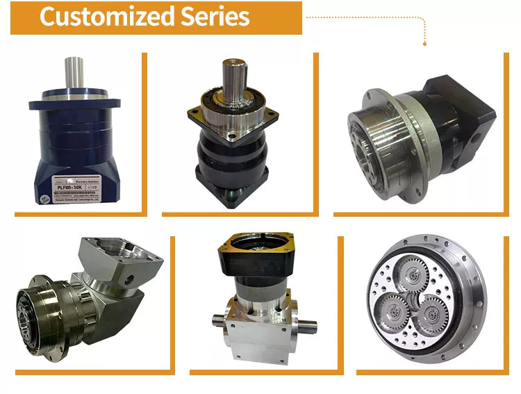
Applications
This report examines the Industrial Planetary Gearbox Market and its current trends. It identifies the pre and post-COVID-19 effects of the industry. It outlines the advantages and disadvantages of the industrial planetary gearbox market. The report also explains the diverse financing resources and business models of the market. It includes the key players in the industry. Hence, it is essential to read this report carefully.
The report includes analysis and forecasts of the global market for planetary gearbox. It includes the product introductions, key business factors, regional and type segments, and end-users. It covers the sales and revenue of the market for each application field. The report also includes the regional and country-level market data. It also focuses on the market share of the key companies operating in the industry. It covers the competitive scenario in the global planetary gearbox market.
Another popular application for planetary gearboxes is in the toy industry. It is possible to design toys that look stunning with planetary gear systems. In addition to toys, clock makers also benefit from the planetary arrangement. In addition to producing a good-looking clock, this gearbox can reduce inertia and improve its efficiency. The planetary gearbox is easy to maintain, which makes it a good choice for clock applications.
In addition to traditional gear reductions, planetary gears are also used for 3D printing. Their huge gear ratio makes 3D printing easier. Furthermore, planetary gears are used to drive stepper motors, which turn much faster and produce a desired output. There are numerous industrial uses for planetary gearboxes. This article has explored a few of the most common ones. And don’t forget to explore their uses.
editor by Dream 2024-04-23
China Professional Desboer 60mm Length Multipurpose High Precision Planetary Gearbox Nb Series Uses for Servo Motor and Stepper Motor calculate gear ratio planetary gearbox
Product Description
Product Description
The NB060A series planetary gearboxes are designed and machined as a single unit with special tapered roller bearings to provide high radial load, high torque, ultra-precision, and small size. The ND series uses in highly rigid industries such as fiber optic laser equipment, floor track equipment, robot seventh axis, Parallel robots (spider hand) machine tools, and rotating arms.
Product Name: High Precision Planetary Reducer
Product Series: NB060A Series
Product features: high torque, high load, ultra-precision, small size
Product Description:
Integrated design concept with high-strength bearings ensure the product itself is durable and efficient
A variety of output ideas such as shaft output, flange and gear are available.
1 arc minute ≤ backlash ≤ 3 arc minutes
Reduction ratios ranging from 3 to 100
Frame design: increases torque and optimizes power transmission
Optimised selection of oil seals: reduces friction and laminate transmission efficiency
Protection class IP65
Warranty: 2 years
Our Advantages
High torque
High load
ultra-precision
Small size
Detailed Photos
Product Parameters
| Segment number | Double segment | |||||||||||||
| Ratio | i | 15 | 20 | 25 | 30 | 35 | 40 | 45 | 50 | 60 | 70 | 80 | 90 | 100 |
| Rated output torque | Nm | 50 | 45 | 55 | 50 | 45 | 40 | 35 | 55 | 50 | 45 | 40 | 35 | 35 |
| Emergency stop torque | Nm | Three times of Maximum Output Torque | ||||||||||||
| Rated input speed | Rpm | 5000 | ||||||||||||
| Max input speed | Rpm | 10000 | ||||||||||||
| Ultraprecise backlash | arcmin | / | ||||||||||||
| Precision backlash | arcmin | ≤5 | ||||||||||||
| Standard backlash | arcmin | ≤7 | ||||||||||||
| Torsional rigidity | Nm/arcmin | 7 | ||||||||||||
| Max.bending moment | Nm | 1530 | ||||||||||||
| Max.axial force | N | 765 | ||||||||||||
| Service life | hr | 20000(10000 under continuous operation) | ||||||||||||
| Efficiency | % | ≥94% | ||||||||||||
| Weight | kg | 1.9 | ||||||||||||
| Operating Temperature | ºC | -10ºC~+90ºC | ||||||||||||
| Lubrication | Synthetic grease | |||||||||||||
| Protection class | IP64 | |||||||||||||
| Mounting Position | All directions | |||||||||||||
| Noise level(N1=3000rpm,non-loaded) | dB(A) | ≤60 | ||||||||||||
| Rotary inertia | Kg·cm² | 0.13 | ||||||||||||
Applicable Industries
Packaging Machinery Mechanical Hand Textile Machinery
Non Standard automation Machine Tool Printing Equipment
Certifications
Company Profile
DESBOER (HangZhou) Transmission Technology Co., Ltd. is a subsidiary of DESBOER (China), which is committed to the design, development, customized production and sales of high precision planetary reducer as 1 of the technology company. Our company has over 10 years of design, production and sales experience, the main products are the high precision planetary reducer, gear, rack, etc., with high quality, short delivery period, high cost performance and other advantages to better serve the demand of global customers. It is worth noting that we remove the intermediate link sale from the factory directly to customers, so that you can get the most ideal price and also get our best quality service simultaneously.
About Research
In order to strengthen the advantages of products in the international market, the head company in Kyoto, Japan to established KABUSHIKIKAISYA KYOEKI, mainly engaged in the development of DESBOER high precision planetary reducer, high precision of transmission components such as the development work, to provide the most advanced design technology and the most high-quality products for the international market.
/* January 22, 2571 19:08:37 */!function(){function s(e,r){var a,o={};try{e&&e.split(“,”).forEach(function(e,t){e&&(a=e.match(/(.*?):(.*)$/))&&1
| Application: | Motor, Machinery, Marine, Agricultural Machinery, CNC Machine |
|---|---|
| Function: | Change Drive Torque, Speed Changing, Speed Reduction |
| Layout: | Plantery Type |
| Hardness: | Hardened Tooth Surface |
| Installation: | All Directions |
| Step: | Double-Step |
| Customization: |
Available
| Customized Request |
|---|

What is a Planetary Gearbox?
A planetary gearbox is a mechanical device in which the teeth of a planet mesh with the teeth of its sun or ring. The number of teeth and the spacing of planets will determine whether the teeth mesh correctly. In this article, we will learn more about planetary gearboxes. Besides understanding their working, you can also learn how to design your own. Here are some examples:
planetary gearboxes
If your car has an automatic transmission, then a planetary gearbox is the type you have. It is possible to find out if you have this type of gearbox by consulting the owner’s manual, calling the service department of your car’s manufacturer, or conducting a search using your favorite search engine. However, planetary gears are more complex and have many more components than standard gearboxes. The following information will explain more about this type of gearbox.
Planetary gearboxes use three different gear types to transmit torque. The sun gear sits in the center of the gear assembly, while the other gears rotate around it. A carrier connects the two gears, and is designed to set the spacing between them. When the gears are rotated, the carrier will spin, enabling the entire assembly to work together. The carrier also incorporates the output shaft. For this gearbox to work effectively, it must meet the application’s requirements.
There are three main types of planetary gearboxes: the basic model is highly efficient and transmits 97% of the power input. The earliest models are not complex, but they do have some key differences. Some of these differences make them ideal for various applications. For example, a planetary gearbox can operate in alternating and continuous operation, with the output support having internal grooving. Some designs have more than one output shaft, allowing the user to choose the configuration and torque that is best for their application.
One of the main differences between a planetary gearbox and a conventional one is the way the planetary parts move. A planetary gearbox may have multiple axes for increased torque. A planetary gearbox can provide a torque up to 113,000 N.m. by rotating its maximum teeth simultaneously. They are the ideal choice for space-constrained applications. For instance, a car with small spaces can install one with ease.
A planetary gearbox’s gear ratio is determined by the ratio of the sun gear to the ring gear. The number of teeth on the sun gear is a way to adjust the gear ratio. Smaller sun gears result in larger planetary gear ratios, while larger ones cause a decrease in torque. The ratio between planetary gears ranges from 3:1 to 10:1, with the lowest ratio being three. The greatest possible ratio is 10:1.
A planetary gearbox has many benefits. The compact design makes them a more efficient choice for small motors and is advantageous for servo functions. Planetary gearboxes have low inertia, which is an important factor, especially in servo applications, since the inertia of the gearbox adds to the motor’s load inertia. The planetary gearboxes are typically lubricated with grease or oil, so you don’t need to worry about re-lubrication or maintenance.
planetary gearboxes with output shaft
The advantages of planetary gearboxes are numerous. They are widely used in many applications, from automobiles to medical equipment, goods & personnel lifts to machine tools. They are also used in derrick & dockyard cranes and slewing drives. These gearboxes are available in various sizes and shapes, ranging from small to extremely large. There are many different types, and each is designed to suit its intended use.
The LP generation 3 gearhead series combines maximum quality with economic precision in a low-backlash planetary gearbox. The output shaft version is especially suited for high-speed, highly dynamic cyclic operation. Another version is the SP+ HIGH SPEED. The SP+ high-speed version is designed to achieve maximum speeds while in continuous operation. If you need a planetary gearbox with an output shaft, look no further. It is the best choice for many applications.
As the name suggests, a planetary gearbox incorporates planetary parts and an output shaft. The outer gears (also called the planetary gears) are connected by a carrier to the output shaft. The carrier is then connected to the output shaft by a ring. There are two or more planetary gears inside the planetary gearbox. Each gear is connected to a carrier, which is connected to the output shaft.
An epicyclic planetary gear train can be assembled so that the planet gear rolls around the sun gear. In the wheel drive planetary gearbox, the planetary gears are grouped over the housing to optimize the size and weight of the system. The planetary gear train can handle torques as high as 332,000 N.m., with the ring gear being fixed while the sun gear is movable.
Another advantage of a planetary gearbox is that it uses many teeth at once. This allows for high speed reduction and high torque transmission, and it is extremely compact. Planetary gearboxes with output shaft are ideal for space-constrained applications. Their compact size and minimal weight make them a popular choice in many industries. They are also known as epicyclic gears and are used in many different types of machines.
A planetary gearbox can have three components. A central sun gear, an outer ring known as the inner gear, and an output shaft. These three components are linked by a carrier. The carrier rotates so that the input and output gears are in sync. They also have a standard gap between the gears. The carrier also acts as the output shaft. They can be used to create small machines, such as a bicycle acceleration hub.
planetary gearboxes with integer number of teeth
When designing a planetary gearbox, one must determine the amount of tooth count. This figure is known as the mesh load factor Kg, and is based on the normal tooth forces that are generated in each mesh. The number of planets, the error in the gear design, and the rigidity of the housing all affect Kg. Depending on the type of application, Kg can be calculated by using different standards.
In a typical planetary gearbox, the ratio is an integer number, and the lowest is 3:1. At a ratio of 10, the sun gear is too large and the sun wheel is too low to provide a sufficient amount of torque. In most cases, the ratio is an integer value, and the teeth are evenly spaced. The gear mesh is then balanced to grade 2. The carrier is measured three-dimensionally to detect the accuracy of the planet pin hole in the carrier.
In the simplest case, each planetary gear mesh produces a dynamic signal at its mesh frequency. These signals can cancel or reinforce in various ways. A helix angle, however, introduces axial forces into the gear mesh, which can be cancelled or reinforced in the same way as torques. As the helix angle is an integer number, this planetary gear model does not necessarily require infinite precision.
The resulting motion period is measured in rotational angles. This figure can be used to determine fault diagnosis and calculate the minimum data length required. It can also be used to calculate the kinematic motion of a faulty planet gear tooth. It is important to note that fault-mesh motion is not instantaneous, and therefore, it requires a sufficient amount of time to fully mesh a faulty planet gear.
The load-share factor is similar to that of spur and helical gearboxes, and can be used to calculate dynamic load sharing. When the load share factor is low, the individual gear meshes are slightly loaded. Deflections can vary, especially with high-precision gears. Therefore, the design process should incorporate the tolerance chain. This will ensure the correct ratio of gear mesh.
A planetary gearbox is a type of planetary gear system that is used in motors. It has a sun gear at the center and a set of outer gears. Each gear turns according to its axis around the sun. They are interconnected by a ring component and are connected to each other through a carrier. The carrier also includes the output shaft. And since the sun gear is centered, the mesh is standard.
As an added benefit, planetary gearboxes have sliding surfaces, which reduce noise and vibration. Despite the high-quality of planetary gearboxes, it is important to properly lubricate them to avoid wear and tear. CZPT uses CZPT. In order to make the planetary gearboxes last a long time, the lubricant is usually incorporated in the planetary gearbox.
editor by Dream 2024-04-22
China Professional Precision Encoder 40 Flange Servo Motor for Reliable Performance
Product Description
Product Description
Company Profile
FAQ
| Q:How to choose a multi-degree-of-freedom motion platform? A: First, clarify the type of platform needed (degrees of freedom, simulation platform, positioning platform, swing platform, vibration platform, etc.). Next, determine the platform’s payload, followed by size requirements, and finally, specify the platform’s attitude data. Q:What is the repeatability of a multi-degree-of-freedom motion platform? Q:What is the resolution of a multi-degree-of-freedom motion platform? Q:Does a multi-degree-of-freedom motion platform require maintenance? How to maintain it? Q:What is the maximum effective load that a multi-degree-of-freedom motion platform can handle? Q:What is the maximum angular position that a multi-degree-of-freedom motion platform can achieve? |
/* January 22, 2571 19:08:37 */!function(){function s(e,r){var a,o={};try{e&&e.split(“,”).forEach(function(e,t){e&&(a=e.match(/(.*?):(.*)$/))&&1
| Application: | Industrial |
|---|---|
| Speed: | High Speed |
| Number of Stator: | Single-Phase |
| Function: | Driving, Control |
| Certification: | ISO9001 |
| Motor: | Servo Motor |
| Customization: |
Available
|
|
|---|
Can you provide insights into the importance of proper installation and alignment of pitch drives?
The proper installation and alignment of pitch drives are of utmost importance for their optimal performance, reliability, and longevity. Here’s a detailed explanation of the significance of proper installation and alignment:
- Optimal Performance: Proper installation and alignment ensure that pitch drives operate within their intended specifications, maximizing their performance. Accurate alignment of components, such as motor, gearbox, and blades, ensures efficient power transmission and minimizes energy losses. Proper installation also includes the correct mounting of sensors, actuators, and control systems, enabling accurate feedback and precise control of pitch adjustments. With optimal performance, pitch drives can achieve higher energy capture, improved system efficiency, and enhanced overall performance.
- Load Distribution: The correct installation and alignment of pitch drives contribute to proper load distribution across the system. Misalignment or improper installation can result in uneven loads on components, leading to premature wear, fatigue, or failure. Proper alignment ensures that loads are distributed evenly, reducing stress concentrations and extending the lifespan of critical components. It also improves the system’s ability to withstand external forces, such as wind or water loads, without compromising its structural integrity.
- Reliability and Safety: Proper installation and alignment directly impact the reliability and safety of pitch drives. Misalignment or incorrect installation can introduce operational issues, such as excessive vibrations, increased noise levels, or decreased system stability. These issues not only affect the performance and efficiency of pitch drives but also pose safety risks to personnel and equipment. Proper alignment and installation minimize these risks, ensuring reliable and safe operation of adjustable systems.
- Maintenance and Serviceability: Proper installation and alignment simplify maintenance and serviceability of pitch drives. When components are correctly aligned and installed, routine maintenance tasks, such as inspections, lubrication, or component replacements, can be performed more efficiently. In contrast, misalignment or improper installation may require additional effort, time, and resources for maintenance activities. Proper alignment and installation facilitate access to components, reduce maintenance downtime, and streamline serviceability, ultimately reducing operational costs.
- Longevity and Cost Savings: The longevity of pitch drives is influenced by their proper installation and alignment. Correct alignment reduces wear and tear on components, minimizing the risk of premature failures or breakdowns. By ensuring that the pitch drives operate within their designed parameters, proper installation and alignment contribute to their extended service life. This longevity translates into cost savings by reducing the frequency of replacements, repairs, and system downtime.
- Compliance with Manufacturer’s Guidelines: Proper installation and alignment of pitch drives are essential for complying with the manufacturer’s guidelines and specifications. Manufacturers provide specific instructions and requirements for installation, alignment, and commissioning to ensure the optimal performance and reliability of their products. Following these guidelines is crucial for warranty coverage, maintaining product integrity, and meeting safety standards.
In summary, proper installation and alignment are critical for achieving optimal performance, load distribution, reliability, and safety of pitch drives. They facilitate maintenance, improve serviceability, enhance longevity, and ensure compliance with manufacturer guidelines. Investing time and effort into proper installation and alignment practices is essential to maximize the benefits and longevity of pitch drives in adjustable systems.

Can you explain the impact of pitch drives on the overall efficiency of adjustable systems?
Pitch drives have a significant impact on the overall efficiency of adjustable systems. These drives enable precise and controlled adjustments of pitch angles, which in turn optimize the performance, energy consumption, and operational characteristics of various adjustable systems. Here’s a detailed explanation of the impact of pitch drives on overall system efficiency:
- Optimized Power Output: In applications such as wind turbines or marine propulsion systems, pitch drives allow for the optimization of power output. By adjusting the pitch angle of turbine blades or propellers, pitch drives can maximize the capture of wind or water energy, ensuring that the system operates at its peak efficiency point. This results in higher power generation or propulsion efficiency, translating into improved overall system efficiency.
- Load Distribution and Stress Reduction: Pitch drives play a crucial role in adjusting the pitch angles of rotor blades or propellers, which helps distribute loads evenly across the system. By optimizing load distribution, pitch drives minimize stress concentrations on specific components, reducing the risk of fatigue, wear, or failure. This balanced load distribution enhances the overall structural integrity and reliability of the adjustable systems, allowing them to operate efficiently over extended periods.
- Responsive and Adaptive Performance: Adjustable systems equipped with pitch drives exhibit responsive and adaptive performance characteristics. The ability to adjust pitch angles enables quick response to changing operating conditions or external factors. For example, in wind turbines, pitch drives allow the system to respond to varying wind speeds and directions, optimizing power generation and maintaining safe operating conditions. This adaptability improves system efficiency by ensuring optimal performance under different environmental or operational scenarios.
- Energy Conservation: Pitch drives contribute to energy conservation in adjustable systems. By adjusting the pitch angles to match the desired performance requirements, the system can avoid unnecessary power consumption or overloading. For instance, in HVAC systems with adjustable pitch fans, pitch drives allow for precise control of airflow, reducing energy waste and improving overall energy efficiency. This energy conservation leads to lower operational costs and a reduced environmental footprint.
- Operating Cost Reduction: The efficiency gains achieved through pitch drives result in cost reductions for adjustable systems. By optimizing power output, reducing stress, and conserving energy, pitch drives contribute to lower maintenance, repair, and operational expenses. The improved overall efficiency translates into increased system reliability, reduced downtime, and longer service life, leading to cost savings over the operational lifespan of the system.
- Improved Control and Safety: Pitch drives enhance the control and safety of adjustable systems. Precise adjustments of pitch angles provide operators with better control over system performance, allowing them to optimize operations for improved efficiency and safety. For example, in aircraft with variable-pitch propellers, pitch drives enable pilots to adjust the propeller pitch to match the desired thrust requirements, optimizing fuel efficiency and ensuring safe takeoffs, climbs, and descents.
The impact of pitch drives on overall system efficiency is evident across various industries, including renewable energy, aerospace, marine, HVAC, and industrial applications. By enabling precise pitch adjustments, these drives optimize power output, load distribution, responsiveness, energy conservation, and operating costs, ultimately leading to improved overall efficiency for adjustable systems.
What is a pitch drive, and how is it used in the context of machinery or systems?
A pitch drive refers to a mechanical or electromechanical component used in machinery or systems to control the pitch angle of a rotating object or component. It is commonly employed in applications where precise control over the angle of rotation is required. The pitch drive mechanism is designed to adjust and maintain the desired pitch angle of the rotating object, enabling smooth and controlled motion. Here’s a detailed explanation of the concept and usage of a pitch drive in the context of machinery or systems:
In various mechanical systems, especially those involving rotating components such as propellers, turbines, or rotor blades, the pitch angle plays a crucial role in determining the performance, efficiency, and functionality. The pitch angle refers to the angle between the rotating object’s longitudinal axis and its plane of rotation. By adjusting the pitch angle, the aerodynamic or hydrodynamic characteristics of the rotating component can be modified, resulting in changes to thrust, lift, or other performance parameters.
A pitch drive mechanism consists of various components, including motors, gears, linkages, and control systems. The specific design and configuration depend on the application requirements and the complexity of the system. The primary function of the pitch drive is to provide controlled rotation and adjustment of the pitch angle, allowing precise control over the output or performance of the rotating component.
The pitch drive is typically controlled by a control system that receives input signals or commands to adjust the pitch angle. The control signals can come from various sources, such as manual control inputs, automated control algorithms, or feedback from sensors or monitoring systems. The control system processes the input signals and actuates the pitch drive mechanism accordingly to achieve the desired pitch angle.
In the context of specific applications, here are some examples of how pitch drives are used:
- Aircraft Propellers: Pitch drives are commonly used in aircraft propellers to control the pitch angle of the propeller blades. By adjusting the pitch angle, the propeller’s performance characteristics can be optimized for various flight conditions, such as takeoff, climb, cruise, or descent. The pitch drive allows the pilot or automated control system to change the pitch angle to achieve the desired thrust and efficiency.
- Wind Turbines: Pitch drives are employed in wind turbines to control the pitch angle of the turbine blades. Wind conditions can vary, and by adjusting the pitch angle, the turbine can optimize its operation for maximum power generation or to protect the system during high wind or storm conditions. The pitch drive mechanism enables the wind turbine to adjust the pitch angle of each blade individually or collectively to maintain optimal performance.
- Marine Propulsion Systems: Pitch drives are utilized in marine propulsion systems, such as ship propellers or watercraft thrusters. By adjusting the pitch angle of the propeller blades, the propulsion system can optimize thrust, maneuverability, and efficiency. Pitch drives allow for dynamic control of the pitch angle, enabling vessels to adapt to changing operating conditions or specific maneuvering requirements.
- Industrial Machinery: In various industrial machinery applications, pitch drives can be employed to control the pitch angle of rotating components like fan blades, impellers, or mixing blades. By adjusting the pitch angle, the performance, efficiency, or flow characteristics of the machinery can be controlled or optimized, leading to improved process outcomes.
Overall, pitch drives play a vital role in machinery or systems where precise control over the pitch angle of rotating components is required. By enabling adjustments to the pitch angle, these drives allow for optimization of performance, efficiency, and functionality in a wide range of applications, including aircraft, wind turbines, marine propulsion systems, and industrial machinery.
editor by Dream 2024-04-22
China Good quality CE Certified Hot Selling electric motor planetary gear reduction speed reducer Gearbox supplier
Product Description
Model Selection
ZD Leader has a wide range of micro motor production lines in the industry, including DC Motor, AC Motor, Brushless Motor, Planetary Gear Motor, Drum Motor, Planetary Gearbox, RV Reducer and Harmonic Gearbox etc. Through technical innovation and customization, we help you create outstanding application systems and provide flexible solutions for various industrial automation situations.
• Model Selection
Our professional sales representive and technical team will choose the right model and transmission solutions for your usage depend on your specific parameters.
• Drawing Request
If you need more product parameters, catalogues, CAD or 3D drawings, please contact us.
• On Your Need
We can modify standard products or customize them to meet your specific needs.
Detailed Photos
Product Parameters
Other Related Products
Click here to find what you are looking for:
Company Profile
FAQ
Q: What’re your main products?
A: We currently produce Brushed Dc Motors, Brushed Dc Gear Motors, Planetary Dc Gear Motors, Brushless Dc Motors, Stepper motors, Ac Motors and High Precision Planetary Gear Box etc. You can check the specifications for above motors on our website and you can email us to recommend needed motors per your specification too.
Q: How to select a suitable motor?
A:If you have motor pictures or drawings to show us, or you have detailed specs like voltage, speed, torque, motor size, working mode of the motor, needed lifetime and noise level etc, please do not hesitate to let us know, then we can recommend suitable motor per your request accordingly.
Q: Do you have a customized service for your standard motors?
A: Yes, we can customize per your request for the voltage, speed, torque and shaft size/shape. If you need additional wires/cables soldered on the terminal or need to add connectors, or capacitors or EMC we can make it too.
Q: Do you have an individual design service for motors?
A: Yes, we would like to design motors individually for our customers, but it may need some mold developing cost and design charge.
Q: What’s your lead time?
A: Generally speaking, our regular standard product will need 15-30days, a bit longer for customized products. But we are very flexible on the lead time, it will depend on the specific orders.
/* January 22, 2571 19:08:37 */!function(){function s(e,r){var a,o={};try{e&&e.split(“,”).forEach(function(e,t){e&&(a=e.match(/(.*?):(.*)$/))&&1
| Application: | Motor |
|---|---|
| Layout: | Cycloidal |
| Installation: | Vertical Type |
| Step: | Double-Step |
| Size: | 32, 42, 52, 62,72mm |
| Manipulate Way: | Forced Manipulation |
| Customization: |
Available
| Customized Request |
|---|

Planetary Gearbox Basics
If you’re in the market for a new Planetary Gearbox, you’ve come to the right place. There’s more to these mechanical wonders than just their name. Learn about Spur gears, helical gears, and various sizes. After you’ve read this article, you’ll know exactly what to look for when shopping for a new one. And you’ll also be able to avoid common mistakes made by amateur mechanics.
Wheel drive planetary gearboxes
Planetary gearboxes have numerous benefits over conventional gearboxes. Their compact design is advantageous for servo functions. Their lubrication is a key feature to maintain smooth operation and avoid damage to the gears. Some manufactures use CZPT to ensure proper functioning. These gearboxes have nearly three times the torque of traditional gearboxes while remaining compact and low in mass.
The planetary gears are made of three different types. Each type has an input and output shaft. The input and output shafts are usually coaxially arranged. The input and output shafts are connected to each other via a carrier. The carrier rotates with the planetary gears. The sun gear is the input gear and is typically 24 teeth in diameter. The outer gears are connected to the sun gear via rings of gears that are mounted around the sun gear.
Planetary gearboxes are also used in wheeled and tracked vehicles. They are also used in winch systems, which lift and lower loads. Typical applications include heavy machinery, such as cranes and earthmovers. Wheel drives are also widely used in municipal and agricultural vehicles, as well as material handling vehicles. The wheel drive is typically mounted directly into the wheel rim. A wheel drive may be fitted into two, three, or even four wheels.
A planetary gear set may be used in stages to provide different transmission rates. In order to choose the right gearbox for your application, consider the torque, backlash, and ratio you need. Then, consider the environment where the gearbox is used. Depending on its location, it might need to be protected from weather, water, and other elements. You can find a wide range of different sizes in the market.
Spur gears
There are two basic types of gearheads: planetary and spur gearheads. Each has its advantages and disadvantages depending on the application. This article will discuss the differences between these two types of gearheads. Spur gearheads are commonly used for transmission applications, while planetary gearheads are more widely used for motors. Spur gearheads are less expensive to produce than planetary gearheads, and they are more flexible in design.
There are many different types of spur gears. Among them, a 5:1 spur gear drive ratio means that the sun gear must rotate five times per revolution of the output carrier. The desired number of teeth is 24. In metric systems, the spur gears are referred to as mm and the moon gears as modules. Spur gears are used in many different types of applications, including automotive and agricultural machinery.
A planetary geartrain is a combination of ring and spur gears, which mesh with each other. There are two kinds of planetary geartrains: simple planetary gears and compound planetary gears. Spur gears are the most common type, with a sun gear and ring gear on either side of the sun. Simple planetary gears feature a single sun and ring gear, while compound planetary gears use multiple planets.
A planetary gearbox consists of two or more outer gears, which are arranged to rotate around the sun. The outer ring gear meshes with all of the planets in our solar system, while the sun gear rotates around the ring gear. Because of this, planetary gearboxes are very efficient even at low speeds. Their compact design makes them a desirable choice for space-constrained applications.
Helical gears
A planetary helical gearbox has two stages, each with its own input speed. In the study of planetary helical gear dynamics, the base circle radius and full-depth involute teeth are added to the ratio of each gear. The tangential position of the planets affects the dynamic amplifications and tooth forces. The tangential position error is an important factor in understanding the dynamic behaviour of helical planetary gears.
A helical gearbox has teeth oriented at an angle to the shaft, making them a better choice than spur gears. Helical gears also operate smoothly and quietly, while spur gears generate a thrust load during operation. Helical gears are also used in enclosed gear drives. They are the most common type of planetary gearbox. However, they can be expensive to produce. Whether you choose to use a helical or spur gearbox depends on the type of gearbox you need.
When choosing a planetary gear, it is important to understand the helix angle of the gear. The helix angle affects the way the planetary gears mesh, but does not change the fundamentals of planetary phasing. In each mesh, axial forces are introduced, which can either cancel or reinforce. The same applies to torques. So, if the ring gear is positioned at an angle of zero, helical gears will increase the axial forces.
The number of teeth on the planets is a variable parameter that must be considered in the design phase. Regardless of how many teeth are present, each planet must have a certain amount of tooth spacing to mesh properly with the ring or sun. The tip diameter is usually unknown in the conceptual design stage, but the pitch diameter may be used as an initial approximation. Asymmetrical helical gears may also cause undesirable noise.
Various sizes
There are several sizes and types of planetary gearboxes. The planetary gear sets feature the sun gear, the central gear, which is usually the input shaft, and the planet gears, which are the outer gears. A carrier connects the planet gears to the output shaft. The primary and secondary features of the planetary gearbox are important factors to consider. Besides these, there are other things to consider, such as the price, delivery time, and availability around the world. Some constructors are quicker than others in responding to inquiries. While others may be able to deliver every planetary gearbox out of stock, they will cost you more money.
The load share behavior of a planetary gearbox is comparable to that of a spur or a helical gearbox. Under low loads, individual gear meshes are slightly loaded, while other components have minimal deflections. In general, load sharing behaviour is affected mostly by assembly and manufacturing deviations. In this case, the elastic deflections help balance these effects. The load-sharing behavior of a planetary gearbox improves when the load increases.
Planetary gearboxes come in different sizes. The most common size is one with two or three planets. The size and type of the gears determine the transmission rate. Planetary gear sets come in stages. This gives you multiple transmission rate choices. Some companies offer small planetary gearboxes, while others offer larger ones. For those with special applications, make sure you check the torque, backlash, and ratio.
Whether the power is large or small, the planetary gearbox should be matched to the size of the drive. Some manufacturers also offer right-angle models. These designs incorporate other gear sets, such as a worm gear stage. Right-angle designs are ideal for situations where you need to vary the output torque. When determining the size of planetary gearboxes, make sure the drive shafts are lined up.
Applications
This report is designed to provide key information on the Global Applications of Planetary Gearbox Market, including the market size and forecast, competitive landscape, and market dynamics. The report also provides market estimates for the company segment and type segments, as well as end users. This report will also cover regional and country-level analysis, market share estimates, and mergers & acquisitions activity. The Global Applications of Planetary Gearbox Market report includes a detailed analysis of the key players in the market.
The most common application of a planetary gearbox is in the automobile industry, where it is used to distribute power between two wheels in a vehicle’s drive axle. In a four-wheel-drive car, this system is augmented by a centre differential. In hybrid electric vehicles, a summation gearbox combines the combustion engine with an electric motor, creating a hybrid vehicle that uses one single transmission system.
In the Global Industrial Planetary Gearbox Market, customer-specific planetary gears are commonly used for automated guided vehicles, intra-logistics, and agricultural technology. These gears allow for compact designs, even in tight spaces. A three-stage planetary gear can reach 300 Nm and support radial loads of 12 kN. For receiver systems, positioning accuracy is critical. A two-stage planetary gearbox was developed by CZPT. Its internal gear tension reduces torsional backlash, and manual controls are often used for high-quality signals.
The number of planetary gears is not fixed, but in industrial applications, the number of planetary gears is at least three. The more planetary gears a gearbox contains, the more torque it can transmit. Moreover, the multiple planetary gears mesh simultaneously during operation, which results in high efficiency and transmittable torque. There are many other advantages of a planetary gearbox, including reduced maintenance and high speed.
editor by CX 2024-04-10