Product Description
Product Description
GP60A traverse box rolling ring drive for wire spooling machine
Manufacturer of automatic linear transmission gear with well-equipped testing facilities and strong technical force
| Type | GP60A |
| Shaft Diameter | 60 mm |
| Number of Rolling Rings | 3 Pieces |
| Maximum Thrust(N) | 1000 N |
| Weight-Bearing(KG) | 100 kg |
| Maximum Pitch(mm) | 48 mm |
| Weight(KG) | 42 kg |
Product Parameters
Detailed Photos
ROTATION DIRECTION (CAN CHANGE)
Packaging & Shipping
|
Package Material
|
Wooden Box or Carton |
|
Package Detail
|
1piece or 5 pieces per carton package or wooden carton |
|
Delivery Way
|
Deliver the goods by express, like UPS, DHL, FedEx or by sea shipment or according to customer’s requirement |
Product Application
Rolling ring drive/ traverse unit device is mostly used in industry. Used in textile machine, wire spooling machine, traverse winding machine, wire winding machine, linear drive system, medical equipment, etc.
Different Type of Product
Rolling Ring Drive has GPA, GPB, CHINAMFG Series, It is widely used in wire,steel wire,electrical wire, cable, textile industry etc.
A Series : Rolling ring drives Type A Series just have 1 rolling ring linear drive box , which are divided into six types according to the diameter of the shafts.
B Series: Rolling ring drives Type B Series have One Rolling Ring linear drive with Xihu (West Lake) Dis. Rollers or Xihu (West Lake) Dis. Wheel , which are divided into 6 types according to the diameter of the shafts.
C Series : Rolling ring drives Type C Series have One Rolling Ring linear drive with accessories, such as shaft,guide roller,bearing block,steady bar,etc , which are divided into six types according to the diameter of the shafts.
FAQ
Q1. What is your terms of packing?
A: Generally, we pack our goods in carton boxes or wooden boxes.
Q2. What is your terms of payment?
A: T/T 100% paymeny in advance, or 30% as deposit, and 70% before delivery. We’ll show you the photos of the products and packages before you pay the balance.
Q3. What is your terms of delivery?
A: EXW, FOB, CFR, CIF, DDU.
Q4. How about your delivery time?
A: Generally, it will send this product within 3 or 5 days after receiving your payment. The specific delivery time depends on the items and the quantity of your order.
Q5. What is your sample policy?
A: We can supply the sample if we have ready parts in stock, but the customers have to pay the sample cost and the courier cost.
Q6. Do you test all your goods before delivery?
A: Yes, we have 100% test before delivery
Q7: How do you make our business long-term and good relationship?
A:1. We keep good quality and competitive price to ensure our customers benefit ;
2. We respect every customer as our friend and we sincerely do business and make friends with them, no matter where they come from.
/* January 22, 2571 19:08:37 */!function(){function s(e,r){var a,o={};try{e&&e.split(“,”).forEach(function(e,t){e&&(a=e.match(/(.*?):(.*)$/))&&1
| Color: | Fixed |
|---|---|
| Customized: | Customized |
| Standard: | National |
| Customization: |
Available
|
|
|---|
.shipping-cost-tm .tm-status-off{background: none;padding:0;color: #1470cc}
|
Shipping Cost:
Estimated freight per unit. |
about shipping cost and estimated delivery time. |
|---|
| Payment Method: |
|
|---|---|
|
Initial Payment Full Payment |
| Currency: | US$ |
|---|
| Return&refunds: | You can apply for a refund up to 30 days after receipt of the products. |
|---|

How do electronic or computer-controlled components integrate with pitch drives in modern applications?
Electronic or computer-controlled components play a crucial role in the integration of pitch drives in modern applications. These components enable precise control, monitoring, and coordination of pitch adjustments, enhancing the performance, efficiency, and safety of adjustable systems. Here’s a detailed explanation of how electronic or computer-controlled components integrate with pitch drives in modern applications:
- Control Systems: Electronic control systems are used to regulate and coordinate the operation of pitch drives. These systems receive input signals, such as wind speed, power demand, or operator commands, and translate them into control signals that govern the pitch angle adjustments. The control systems monitor the system’s operating conditions and adjust the pitch drives accordingly to maintain optimal performance, efficiency, and safety.
- Sensors: Sensors are integrated with pitch drives to provide real-time feedback on various parameters. For example, wind turbines may incorporate wind speed sensors, blade position sensors, or load sensors to continuously monitor the environmental conditions and system response. The sensor data is fed into the control system, allowing it to make informed decisions regarding pitch adjustments. Sensors enable precise control and ensure that the pitch drives respond accurately to changing conditions.
- Actuators: Actuators are electronic or electromechanical devices that convert control signals from the control system into physical motion. In the context of pitch drives, actuators are responsible for adjusting the pitch angles of blades, propellers, or other adjustable components. The control system sends signals to the actuators, specifying the desired pitch angle, and the actuators actuate the pitch drives accordingly. Actuators enable precise and dynamic control over the pitch adjustments, contributing to the overall performance and efficiency of the adjustable systems.
- Communication and Networking: Electronic or computer-controlled components facilitate communication and networking capabilities in modern pitch drive applications. They enable data exchange between the control system, sensors, actuators, and other system components. This communication allows for coordinated operation, data logging, remote monitoring, and integration with higher-level control systems or supervisory systems. Networking technologies, such as Ethernet, CAN bus, or wireless protocols, facilitate efficient data transmission and system integration.
- Embedded Systems and Microcontrollers: Embedded systems and microcontrollers are often employed in modern pitch drive applications. These compact and powerful computing devices are dedicated to performing specific control and monitoring tasks. They execute control algorithms, handle sensor inputs, and generate actuator outputs in real-time. Embedded systems and microcontrollers provide the computational power and responsiveness required for precise and reliable control of pitch drives.
- Data Analysis and Optimization: Electronic or computer-controlled components enable data analysis and optimization techniques for pitch drives. They can collect and process data from various sensors and feedback loops to identify performance trends, detect anomalies, and optimize control strategies. This data-driven approach allows for continuous improvement of system performance, energy efficiency, and predictive maintenance.
The integration of electronic or computer-controlled components with pitch drives in modern applications enables advanced functionality, flexibility, and performance optimization. By integrating control systems, sensors, actuators, communication capabilities, embedded systems, and data analysis techniques, adjustable systems can achieve precise control, adaptive response, and efficient operation, resulting in enhanced overall performance and functionality.

How does the choice of materials impact the performance of pitch drives in different environments?
The choice of materials plays a significant role in determining the performance of pitch drives, particularly in different environments. The materials used in pitch drives directly impact factors such as durability, reliability, efficiency, and resistance to environmental conditions. Here’s a detailed explanation of how the choice of materials impacts the performance of pitch drives in different environments:
- Durability and Mechanical Strength: The materials used in pitch drives must possess high durability and mechanical strength to withstand the forces and loads experienced during operation. The choice of materials with excellent tensile strength, fatigue resistance, and resistance to wear can help ensure the longevity and reliability of the pitch drives, especially in demanding environments where high loads, vibrations, or abrasive particles may be present.
- Corrosion Resistance: In environments where pitch drives are exposed to moisture, saltwater, or corrosive substances, the choice of materials with high corrosion resistance is crucial. Corrosion can degrade the performance and structural integrity of pitch drives over time. Materials such as stainless steel, corrosion-resistant alloys, or specialized coatings can be employed to mitigate the effects of corrosion and maintain the performance and reliability of the pitch drives in such environments.
- Temperature Resistance: Different environments can subject pitch drives to extreme temperature variations. The materials used in pitch drives should have appropriate temperature resistance properties to ensure consistent performance across a wide temperature range. For example, in high-temperature environments, materials with high heat resistance, such as heat-resistant alloys or ceramics, may be employed to prevent deformation or degradation of the pitch drives.
- Environmental Contaminants: Some environments may contain contaminants, such as dust, dirt, or chemicals, which can impact the performance of pitch drives. The choice of materials that are resistant to the specific environmental contaminants encountered in a particular application can help maintain the functionality and reliability of the pitch drives. Materials with low friction coefficients or self-cleaning properties may be preferred to minimize the accumulation of contaminants on critical components.
- Weight and Inertia: The choice of materials in pitch drives can also impact their weight and inertia. Lighter materials with high strength-to-weight ratios can reduce the overall weight of the pitch drives, resulting in improved energy efficiency and reduced mechanical stress. Additionally, materials with low inertia can enhance the responsiveness and agility of the pitch drives, allowing for faster pitch adjustments and precise control in dynamic operating conditions.
- Electrical and Thermal Conductivity: In pitch drives that incorporate electrical or thermal components, such as sensors, actuators, or cooling systems, the choice of materials can impact electrical and thermal conductivity. Materials with appropriate electrical and thermal conductivity properties can facilitate efficient heat dissipation, electrical signal transmission, or electromagnetic interference (EMI) shielding, ensuring optimal performance and minimizing the risk of electrical or thermal issues.
It’s important to note that the choice of materials should be based on a thorough understanding of the specific environmental conditions and operational requirements of the pitch drives. Factors such as cost-effectiveness, manufacturability, and compatibility with other components or subsystems should also be considered.
In summary, the choice of materials in pitch drives significantly impacts their performance in different environments. Materials with high durability, corrosion resistance, temperature resistance, resistance to environmental contaminants, appropriate weight and inertia, and suitable electrical and thermal conductivity properties can ensure optimal performance, reliability, and longevity of pitch drives in various operating conditions.

What are the different types and configurations of pitch drives available in the market?
There are several different types and configurations of pitch drives available in the market, each designed to suit specific applications and requirements. These pitch drives vary in their mechanisms, actuation methods, and configurations. Here’s a detailed explanation of the different types and configurations of pitch drives:
1. Hydraulic Pitch Drives: Hydraulic pitch drives use hydraulic actuators to control the pitch angle. They typically consist of hydraulic cylinders or hydraulic motors connected to the rotating components. Hydraulic systems offer high force or torque output, precise control, and the ability to handle heavy loads. Hydraulic pitch drives are commonly used in large-scale applications such as wind turbines and marine propulsion systems.
2. Pneumatic Pitch Drives: Pneumatic pitch drives utilize pneumatic actuators, such as pneumatic cylinders, to adjust the pitch angle. They operate by using compressed air or gas to generate the necessary force or torque. Pneumatic pitch drives are often employed in applications where a clean and dry power source is required, or in situations where hydraulic systems are not feasible or preferred.
3. Electric Pitch Drives: Electric pitch drives employ electric actuators, such as electric motors or electric linear actuators, to control the pitch angle. They can be powered by AC or DC electricity and offer precise control, high responsiveness, and flexibility in terms of control algorithms and integration with control systems. Electric pitch drives are commonly found in aircraft propellers, small wind turbines, and industrial machinery.
4. Mechanical Pitch Drives: Mechanical pitch drives utilize mechanical linkages, gears, or cam mechanisms to adjust the pitch angle. They convert rotational motion to linear or angular displacement for pitch adjustment. Mechanical pitch drives are often used in small-scale applications where simplicity, compactness, and lightweight design are essential. They can be found in small wind turbines, model aircraft, or mechanical systems with lower power requirements.
5. Linear Pitch Drives: Linear pitch drives are designed to achieve linear pitch angle adjustment instead of rotational. They utilize linear actuators, such as electric linear actuators or hydraulic cylinders, to extend or retract the pitch mechanism in a linear motion. Linear pitch drives are commonly used in applications where linear movement is required, such as certain types of propellers or control surfaces.
6. Individual Blade Pitch Drives: Individual blade pitch drives allow for independent control and adjustment of each blade in multi-blade systems. They enable optimized performance and load distribution across the blades, especially in applications such as wind turbines or helicopter rotor systems. Individual blade pitch drives can be hydraulic, pneumatic, or electric, depending on the specific requirements and complexity of the system.
7. Collective Pitch Drives: Collective pitch drives adjust the pitch angle of all blades simultaneously. They are commonly used in applications where coordinated pitch adjustments are necessary, such as helicopter main rotors or certain types of wind turbines. Collective pitch drives can be hydraulic, pneumatic, or electric, depending on the system’s design and requirements.
8. Integrated Control Systems: Some pitch drives come with integrated control systems, which include sensors, signal processing units, and control algorithms. These integrated control systems allow for automated and precise pitch angle adjustment based on various input parameters, such as wind speed, rotational speed, or pilot commands. Integrated control systems enhance the efficiency, safety, and overall performance of pitch drives in various applications.
It’s important to note that the availability and suitability of different types and configurations of pitch drives may vary depending on the specific industry, application, and technological advancements. Manufacturers and suppliers in the market offer a range of pitch drive options to cater to different needs and requirements.


editor by CX 2024-03-29
China high quality Wire Twisting Machine Assembly Gp15b Traverse Unit Rolling Ring Drive
Product Description
Product Description
Wire twisting machine assembly GP15B traverse unit rolling ring drive
Manufacturer of automatic linear transmission gear with well-equipped testing facilities and strong technical force
| Type | GP15B |
| Shaft Diameter | 15 mm |
| Number of Rolling Rings | 3 Pieces |
| Maximum Thrust(N) | 100 N |
| Weight-Bearing(KG) | 10 kg |
| Maximum Pitch(mm) | 11 mm |
| Weight(KG) | 1.5 kg |
Product Parameters
Detailed Photos
ROTATION DIRECTION (CAN CHANGE)
Packaging & Shipping
|
Package Material
|
Wooden Box or Carton |
|
Package Detail
|
1piece or 5 pieces per carton package or wooden carton |
|
Delivery Way
|
Deliver the goods by express, like UPS, DHL, FedEx or by sea shipment or according to customer’s requirement |
Product Application
Rolling ring drive/ traverse unit device is mostly used in industry. Used in textile machine, wire spooling machine, traverse winding machine, wire winding machine, linear drive system, medical equipment, etc.
Different Type of Product
Rolling Ring Drive has GPA, GPB, CHINAMFG Series, It is widely used in wire,steel wire,electrical wire, cable, textile industry etc.
A Series : Rolling ring drives Type A Series just have 1 rolling ring linear drive box , which are divided into six types according to the diameter of the shafts.
B Series: Rolling ring drives Type B Series have One Rolling Ring linear drive with Xihu (West Lake) Dis. Rollers or Xihu (West Lake) Dis. Wheel , which are divided into 6 types according to the diameter of the shafts.
C Series : Rolling ring drives Type C Series have One Rolling Ring linear drive with accessories, such as shaft,guide roller,bearing block,steady bar,etc , which are divided into six types according to the diameter of the shafts.
FAQ
Q1. What is your terms of packing?
A: Generally, we pack our goods in carton boxes or wooden boxes.
Q2. What is your terms of payment?
A: T/T 100% paymeny in advance, or 30% as deposit, and 70% before delivery. We’ll show you the photos of the products and packages before you pay the balance.
Q3. What is your terms of delivery?
A: EXW, FOB, CFR, CIF, DDU.
Q4. How about your delivery time?
A: Generally, it will send this product within 3 or 5 days after receiving your payment. The specific delivery time depends on the items and the quantity of your order.
Q5. What is your sample policy?
A: We can supply the sample if we have ready parts in stock, but the customers have to pay the sample cost and the courier cost.
Q6. Do you test all your goods before delivery?
A: Yes, we have 100% test before delivery
Q7: How do you make our business long-term and good relationship?
A:1. We keep good quality and competitive price to ensure our customers benefit ;
2. We respect every customer as our friend and we sincerely do business and make friends with them, no matter where they come from.
/* January 22, 2571 19:08:37 */!function(){function s(e,r){var a,o={};try{e&&e.split(“,”).forEach(function(e,t){e&&(a=e.match(/(.*?):(.*)$/))&&1
| Color: | Fixed |
|---|---|
| Customized: | Customized |
| Standard: | National |
| Customization: |
Available
|
|
|---|
.shipping-cost-tm .tm-status-off{background: none;padding:0;color: #1470cc}
|
Shipping Cost:
Estimated freight per unit. |
about shipping cost and estimated delivery time. |
|---|
| Payment Method: |
|
|---|---|
|
Initial Payment Full Payment |
| Currency: | US$ |
|---|
| Return&refunds: | You can apply for a refund up to 30 days after receipt of the products. |
|---|

What safety considerations should be taken into account when using pitch drives in industrial settings?
When using pitch drives in industrial settings, several safety considerations should be taken into account to ensure the well-being of personnel, the protection of equipment, and the prevention of accidents. Here’s a detailed explanation of the safety considerations associated with the use of pitch drives in industrial settings:
- Training and Competence: Proper training and competence of personnel operating and maintaining pitch drives are essential for safety. Adequate training should be provided to ensure that operators and maintenance personnel understand the operating principles, safety procedures, and potential hazards associated with pitch drives. Competent personnel can effectively identify and respond to safety risks, perform maintenance tasks safely, and mitigate potential accidents or malfunctions.
- Protective Measures: Industrial settings utilizing pitch drives should incorporate appropriate protective measures to minimize the risk of accidents and injuries. This includes the installation of physical barriers, guards, or enclosures around pitch drive components to prevent unauthorized access and protect personnel from moving parts. Safety interlocks and emergency stop systems should also be in place to quickly halt pitch drive operation in case of emergencies or abnormal conditions.
- Electrical Safety: Pitch drives in industrial settings typically involve electrical components and connections. Electrical safety measures should be observed, including proper grounding, insulation, and protection against electrical hazards. Qualified electricians should handle electrical installations, and regular inspections should be conducted to ensure the integrity of electrical systems associated with pitch drives.
- Lockout/Tagout Procedures: Lockout/tagout procedures are crucial when performing maintenance, repair, or inspection tasks on pitch drives. These procedures ensure that energy sources are isolated, locked, and tagged to prevent accidental startup or release of stored energy. Lockout/tagout procedures should be strictly followed to protect personnel from electrical shocks, unexpected movements, or hazardous conditions during maintenance activities.
- Risk Assessment and Hazard Identification: A comprehensive risk assessment should be conducted to identify potential hazards and assess the associated risks in industrial settings using pitch drives. This includes evaluating risks related to electrical hazards, mechanical hazards, ergonomic factors, and environmental factors. By identifying and understanding the specific risks, appropriate control measures can be implemented to minimize or eliminate hazards and reduce the likelihood of accidents or injuries.
- Maintenance and Inspections: Regular maintenance and inspections are critical for ensuring the safe operation of pitch drives in industrial settings. Scheduled maintenance tasks, such as lubrication, alignment checks, and component replacements, should be performed according to manufacturer recommendations and industry standards. Inspections should be conducted to identify any signs of wear, damage, or deterioration that may compromise the safety and reliability of pitch drives.
- Emergency Preparedness: Adequate emergency preparedness measures should be in place to respond to potential accidents or malfunctions involving pitch drives. This includes having well-defined emergency procedures, trained personnel, and appropriate safety equipment readily available. Emergency response drills and exercises can help familiarize personnel with the necessary actions to take during emergency situations and ensure a prompt and effective response.
- Compliance with Standards and Regulations: Industrial settings should comply with relevant safety standards, regulations, and codes when using pitch drives. These standards may include electrical safety standards, machinery safety standards, and occupational health and safety regulations. Compliance ensures that safety requirements are met, and best practices are followed to protect personnel and maintain a safe working environment.
In summary, safety considerations are of utmost importance when using pitch drives in industrial settings. Training and competence, protective measures, electrical safety, lockout/tagout procedures, risk assessment, maintenance and inspections, emergency preparedness, and compliance with standards and regulations are key aspects to address. By implementing these safety considerations, industrial settings can mitigate risks, prevent accidents, and create a safer environment for personnel and equipment when using pitch drives.
How does the choice of materials impact the performance of pitch drives in different environments?
The choice of materials plays a significant role in determining the performance of pitch drives, particularly in different environments. The materials used in pitch drives directly impact factors such as durability, reliability, efficiency, and resistance to environmental conditions. Here’s a detailed explanation of how the choice of materials impacts the performance of pitch drives in different environments:
- Durability and Mechanical Strength: The materials used in pitch drives must possess high durability and mechanical strength to withstand the forces and loads experienced during operation. The choice of materials with excellent tensile strength, fatigue resistance, and resistance to wear can help ensure the longevity and reliability of the pitch drives, especially in demanding environments where high loads, vibrations, or abrasive particles may be present.
- Corrosion Resistance: In environments where pitch drives are exposed to moisture, saltwater, or corrosive substances, the choice of materials with high corrosion resistance is crucial. Corrosion can degrade the performance and structural integrity of pitch drives over time. Materials such as stainless steel, corrosion-resistant alloys, or specialized coatings can be employed to mitigate the effects of corrosion and maintain the performance and reliability of the pitch drives in such environments.
- Temperature Resistance: Different environments can subject pitch drives to extreme temperature variations. The materials used in pitch drives should have appropriate temperature resistance properties to ensure consistent performance across a wide temperature range. For example, in high-temperature environments, materials with high heat resistance, such as heat-resistant alloys or ceramics, may be employed to prevent deformation or degradation of the pitch drives.
- Environmental Contaminants: Some environments may contain contaminants, such as dust, dirt, or chemicals, which can impact the performance of pitch drives. The choice of materials that are resistant to the specific environmental contaminants encountered in a particular application can help maintain the functionality and reliability of the pitch drives. Materials with low friction coefficients or self-cleaning properties may be preferred to minimize the accumulation of contaminants on critical components.
- Weight and Inertia: The choice of materials in pitch drives can also impact their weight and inertia. Lighter materials with high strength-to-weight ratios can reduce the overall weight of the pitch drives, resulting in improved energy efficiency and reduced mechanical stress. Additionally, materials with low inertia can enhance the responsiveness and agility of the pitch drives, allowing for faster pitch adjustments and precise control in dynamic operating conditions.
- Electrical and Thermal Conductivity: In pitch drives that incorporate electrical or thermal components, such as sensors, actuators, or cooling systems, the choice of materials can impact electrical and thermal conductivity. Materials with appropriate electrical and thermal conductivity properties can facilitate efficient heat dissipation, electrical signal transmission, or electromagnetic interference (EMI) shielding, ensuring optimal performance and minimizing the risk of electrical or thermal issues.
It’s important to note that the choice of materials should be based on a thorough understanding of the specific environmental conditions and operational requirements of the pitch drives. Factors such as cost-effectiveness, manufacturability, and compatibility with other components or subsystems should also be considered.
In summary, the choice of materials in pitch drives significantly impacts their performance in different environments. Materials with high durability, corrosion resistance, temperature resistance, resistance to environmental contaminants, appropriate weight and inertia, and suitable electrical and thermal conductivity properties can ensure optimal performance, reliability, and longevity of pitch drives in various operating conditions.

Can you describe the factors to consider when selecting pitch drives for specific applications?
When selecting pitch drives for specific applications, several factors need to be considered to ensure optimal performance, reliability, and efficiency. The suitability of a pitch drive depends on the requirements of the application, the operating conditions, and the desired performance objectives. Here’s a detailed explanation of the factors to consider when selecting pitch drives for specific applications:
- Power Requirements: The power requirements of the application play a crucial role in pitch drive selection. It is essential to determine the required force or torque output to adjust the pitch angle effectively. Considerations should include the load characteristics, operating speed, and the ability of the pitch drive to handle the power demands of the system.
- Control and Precision: The level of control and precision needed for pitch angle adjustments is another critical factor. Some applications require high accuracy and responsiveness, while others may tolerate lower precision. Consider the required control resolution, response time, and the ability of the pitch drive to maintain the desired pitch angle within specified tolerances.
- Environmental Conditions: Environmental conditions, such as temperature, humidity, dust, and vibration levels, can significantly impact the performance and durability of pitch drives. Evaluate the operating environment and ensure that the pitch drive is designed to withstand and operate reliably under the specific environmental conditions of the application.
- Load Capacity and Dynamics: Consider the load capacity and dynamics of the application. Evaluate the maximum loads that the pitch drive needs to handle and ensure that it can provide the necessary force or torque output. Additionally, consider the dynamic behavior of the application, including acceleration, deceleration, and cyclic load variations, and select a pitch drive that can withstand the expected load dynamics.
- Space and Weight Constraints: Space limitations and weight constraints may influence the selection of a pitch drive, especially in applications with confined spaces or weight-sensitive systems. Consider the physical dimensions, weight, and compactness of the pitch drive to ensure it can be appropriately integrated into the system without compromising other design requirements.
- Reliability and Maintenance: Reliability is crucial in many applications, particularly in critical systems where downtime can have severe consequences. Evaluate the reliability track record of the pitch drive and consider factors such as maintenance requirements, expected lifespan, and availability of spare parts. Additionally, consider the ease of maintenance and the availability of technical support or service from the manufacturer or supplier.
- Cost and Budget: Cost considerations are essential when selecting a pitch drive. Evaluate the initial purchase cost, installation costs, and any additional costs associated with integrating the pitch drive into the system. Also, consider the long-term operating costs, including maintenance, energy consumption, and potential future upgrades or replacements.
- Compatibility and Integration: Ensure compatibility and smooth integration of the pitch drive with the existing system or components. Consider factors such as mounting options, interface requirements, control system compatibility, and the feasibility of integrating the pitch drive seamlessly into the application.
- Industry and Application-specific Requirements: Different industries and applications may have specific requirements or standards that need to be met. For example, wind turbine pitch drives may need to comply with industry standards and certifications. Evaluate any industry-specific requirements and ensure that the selected pitch drive meets the necessary criteria.
By carefully considering these factors, it is possible to select a pitch drive that is well-suited for the specific application, delivering optimal performance, reliability, and efficiency.
editor by CX 2024-03-29
China supplier 711c3b50c094h2d5w1a52mhhyd Bonfiglio Travel Drive Planetary Gearboxes Mt711c115 nema 23 planetary gearbox
Product Description
711C3B50C094H2D5W1A52MHHYD Bonfiglio Travel Drive Planetary Gearboxes.Transmission Bonfiglioli 711C3B 1/715 CF.
Bonfigli Superior Torque Travel Drive Planetary 709 709C3B 710C3B 711C3B 713C3B 715C3B 716C3B 717C3B paver track reducer
Hydraulic drive radial piston MT711C115motor MS02 MSE02 MS05 MS08 MS11 MS18 MS25 MS50 MS83 For sale
radial piston hydraulic EPIROC motor spare parts
The MS/MSE series motor can be added all kinds of hydraulic valves, mechanical brake, wheel output shaft and other components, motor can make a double displacement, multi-functions collocation can meet the needs of users in various fields.
The MS/MSE hydraulic motor is widely used in shearer, skid steer loaders, DTH drill, rotary drilling ilg, small road header, mixer, cutting machine, heavy duty handling car,cavenging machine, aircraft tractor, beam carrier,hoisting machineport crane,boring machine, scraper, mini farming vehicle, ditcher,heavy-duty truck and coal mine drilling machine.
100% interchangeable with original MT711C112 MT711C113 MS/MSE series 02/05/08/11/18/25/35/50/83/125/250 motors!
711C3B 713C3B 715C3B 716C3B 717C3H 718C3H 720C3H 722C3H. CZPT . 603W 605W 606W 607W 609W 606W2/3 610W2/3 611W2/3 610W 611W 613 W.
MS18 Hydraulic Piston Motor:
Low speed Large torque Hydraulic motor,
Radial piston type,
Adopt Imported Bearing and Oil Seal,
Modular design, High efficiency, High pressure and smooth running even at very low speeds,
Permissible Radial and Axial load, Motor with multi-disc brake, Motor emission control,
Applications:
As revolution mechanism of hydraulic system, used for forklift, skid steer loader, grab,
metallurgy mine equipment, shipping port equipment, hydraclic winch, etc.
|
Type |
MS18-8 |
MS18-9 |
MS18-0 |
MS18-1 |
MS18-2 |
|||||
|
Displacement(ml/r) |
Full |
Semi |
Full |
Semi |
Full |
Semi |
Full |
Semi |
Full |
Semi |
|
1395 |
697 |
1571 |
785 |
1747 |
873 |
1911 |
955 |
2099 |
1049 |
|
|
Max power(kw) |
62 |
42 |
62 |
42 |
62 |
42 |
62 |
42 |
62 |
42 |
|
Pressure discrepancy 10MPa Torque |
2085 |
1571 |
2348 |
1151 |
2611 |
1279 |
2856 |
1400 |
3137 |
1537 |
|
Rated torque(N. m) |
5212 |
5870 |
6528 |
7140 |
7843 |
|||||
|
Rated pressure(MPa) |
25 |
25 |
25 |
25 |
25 |
|||||
|
Max pressure(MPa) |
40 |
40 |
40 |
35 |
35 |
|||||
|
Rated speed(r/min) |
55 |
55 |
55 |
55 |
50 |
|||||
|
Speed range(r/min) |
0-150 |
0-150 |
0-150 |
0-135 |
0-125 |
|||||
road roller gearbox
IFT017D2571W GEARBOX for CZPT Drilling RIG Winch China
Product Application Gft110W3b115-06
Rexroth GFT 110 GFT80 Hydraulic Reducers For Concrete Mixers
Excavators CZPT Final Winch Drive Gearbox GFT 110 GFT80 Reducers
GFT80 GFT160 Reducer Gearbox CZPT Hydraulic Gearbox For Excavators
GFT walking reducer is widely used in rotary drilling rig walking, the main winch, small size, compact structure, large output torque, easy installation, direct connection with the walking tire,
GFT hydrostatic transmission (travel reducer / travel motor) is a gear or chain drive vehicles and other mobile devices ideal drive. In addition, where there is movement, rotation and rotation are applicable. Due to its particularly compact construction, the GFT transmission can also be used where the installation environment is extremely difficult. The use of surface hardened gears and quenched and tempered and surface nitrided gears, coupled with good manufacturing quality, enables the device to have excellent load carrying capacity and operational reliability.
Brake: Spring loaded, hydraulically released spring pressure in the actuator – Multi-disc – Stop brake. Collectively: multi-chip parking brake. Whenever necessary, even at the project stage, we are always ready to advise you on how to find the most suitable solution for you.
HangZhou Yuan Yi Hydraulic Equipment Co., Ltd. is located in the provincial capital of HangZhou, ZheJiang Province, agents and distribution of foreign CZPT brands Rexroth, Sauer
Hydraulic control components of the technology-oriented enterprises. Committed to providing customers with high-quality hydraulic control components and hydraulic system design, maintenance, etc.
Surface services. The company has long been CZPT with foreign hydraulic enterprises to maintain close cooperative partnership to ensure that the original products for customers; for customers
To provide rapid response and comprehensive pre-sale, sales, after-sales service; provide reasonable, preferential products. Company’s main products are: import CZPT
, CZPT ATLAS CZPT RIG GEARBOX hydraulic piston pumps, motors, gear pumps, reducer assembly and accessories. China-made CZPT brands Xihu (West Lake) Dis. hydraulic professional sales. public
Division customers in the mixing truck, underground scraper, grain combine harvesters, ship machinery, concrete pump truck, coal mining machinery, road rollers,
Paver, port machinery, oilfield machinery, rotary drilling rig and other industries supporting the application.
Package product:
MF21, PV22, MF22, PV23, MF23, and so on, which are widely used in agriculture, forestry, agriculture,
MV23, PV23 + PV23 double piston pump, and motor.
Acting Sales:
EPIROC Rexroth: A2F, A6V, A7V, A8V, A11VO, A4VG, A10VSO.
Kawasaki: K3V, K3VG, K5V.
Linde: HPV-02, HPR-02, HMF-02, HMV-02.
SAUER: 90 series, 40 series, 45 series, 20 series, such as assembly and accessories
Companies to undertake professional import hydraulic pump, motor repair, commissioning, and provide free advisory services.
Construction machinery:
Digging machine, paver, road roller, press, paver, drilling machine, bulldozer, heavy CZPT machine, road mixer and so on.
/* January 22, 2571 19:08:37 */!function(){function s(e,r){var a,o={};try{e&&e.split(“,”).forEach(function(e,t){e&&(a=e.match(/(.*?):(.*)$/))&&1
| Layout: | Cycloidal |
|---|---|
| Hardness: | Hardened Tooth Surface |
| Installation: | Torque Arm Type |
| Step: | Three-Step |
| Type: | Cylindrical Gear Box |
| Transport Package: | Wood Cases |
| Customization: |
Available
| Customized Request |
|---|

Planetary Gearbox Basics
If you’re in the market for a new Planetary Gearbox, you’ve come to the right place. There’s more to these mechanical wonders than just their name. Learn about Spur gears, helical gears, and various sizes. After you’ve read this article, you’ll know exactly what to look for when shopping for a new one. And you’ll also be able to avoid common mistakes made by amateur mechanics.
Wheel drive planetary gearboxes
Planetary gearboxes have numerous benefits over conventional gearboxes. Their compact design is advantageous for servo functions. Their lubrication is a key feature to maintain smooth operation and avoid damage to the gears. Some manufactures use CZPT to ensure proper functioning. These gearboxes have nearly three times the torque of traditional gearboxes while remaining compact and low in mass.
The planetary gears are made of three different types. Each type has an input and output shaft. The input and output shafts are usually coaxially arranged. The input and output shafts are connected to each other via a carrier. The carrier rotates with the planetary gears. The sun gear is the input gear and is typically 24 teeth in diameter. The outer gears are connected to the sun gear via rings of gears that are mounted around the sun gear.
Planetary gearboxes are also used in wheeled and tracked vehicles. They are also used in winch systems, which lift and lower loads. Typical applications include heavy machinery, such as cranes and earthmovers. Wheel drives are also widely used in municipal and agricultural vehicles, as well as material handling vehicles. The wheel drive is typically mounted directly into the wheel rim. A wheel drive may be fitted into two, three, or even four wheels.
A planetary gear set may be used in stages to provide different transmission rates. In order to choose the right gearbox for your application, consider the torque, backlash, and ratio you need. Then, consider the environment where the gearbox is used. Depending on its location, it might need to be protected from weather, water, and other elements. You can find a wide range of different sizes in the market.
Spur gears
There are two basic types of gearheads: planetary and spur gearheads. Each has its advantages and disadvantages depending on the application. This article will discuss the differences between these two types of gearheads. Spur gearheads are commonly used for transmission applications, while planetary gearheads are more widely used for motors. Spur gearheads are less expensive to produce than planetary gearheads, and they are more flexible in design.
There are many different types of spur gears. Among them, a 5:1 spur gear drive ratio means that the sun gear must rotate five times per revolution of the output carrier. The desired number of teeth is 24. In metric systems, the spur gears are referred to as mm and the moon gears as modules. Spur gears are used in many different types of applications, including automotive and agricultural machinery.
A planetary geartrain is a combination of ring and spur gears, which mesh with each other. There are two kinds of planetary geartrains: simple planetary gears and compound planetary gears. Spur gears are the most common type, with a sun gear and ring gear on either side of the sun. Simple planetary gears feature a single sun and ring gear, while compound planetary gears use multiple planets.
A planetary gearbox consists of two or more outer gears, which are arranged to rotate around the sun. The outer ring gear meshes with all of the planets in our solar system, while the sun gear rotates around the ring gear. Because of this, planetary gearboxes are very efficient even at low speeds. Their compact design makes them a desirable choice for space-constrained applications.
Helical gears
A planetary helical gearbox has two stages, each with its own input speed. In the study of planetary helical gear dynamics, the base circle radius and full-depth involute teeth are added to the ratio of each gear. The tangential position of the planets affects the dynamic amplifications and tooth forces. The tangential position error is an important factor in understanding the dynamic behaviour of helical planetary gears.
A helical gearbox has teeth oriented at an angle to the shaft, making them a better choice than spur gears. Helical gears also operate smoothly and quietly, while spur gears generate a thrust load during operation. Helical gears are also used in enclosed gear drives. They are the most common type of planetary gearbox. However, they can be expensive to produce. Whether you choose to use a helical or spur gearbox depends on the type of gearbox you need.
When choosing a planetary gear, it is important to understand the helix angle of the gear. The helix angle affects the way the planetary gears mesh, but does not change the fundamentals of planetary phasing. In each mesh, axial forces are introduced, which can either cancel or reinforce. The same applies to torques. So, if the ring gear is positioned at an angle of zero, helical gears will increase the axial forces.
The number of teeth on the planets is a variable parameter that must be considered in the design phase. Regardless of how many teeth are present, each planet must have a certain amount of tooth spacing to mesh properly with the ring or sun. The tip diameter is usually unknown in the conceptual design stage, but the pitch diameter may be used as an initial approximation. Asymmetrical helical gears may also cause undesirable noise.
Various sizes
There are several sizes and types of planetary gearboxes. The planetary gear sets feature the sun gear, the central gear, which is usually the input shaft, and the planet gears, which are the outer gears. A carrier connects the planet gears to the output shaft. The primary and secondary features of the planetary gearbox are important factors to consider. Besides these, there are other things to consider, such as the price, delivery time, and availability around the world. Some constructors are quicker than others in responding to inquiries. While others may be able to deliver every planetary gearbox out of stock, they will cost you more money.
The load share behavior of a planetary gearbox is comparable to that of a spur or a helical gearbox. Under low loads, individual gear meshes are slightly loaded, while other components have minimal deflections. In general, load sharing behaviour is affected mostly by assembly and manufacturing deviations. In this case, the elastic deflections help balance these effects. The load-sharing behavior of a planetary gearbox improves when the load increases.
Planetary gearboxes come in different sizes. The most common size is one with two or three planets. The size and type of the gears determine the transmission rate. Planetary gear sets come in stages. This gives you multiple transmission rate choices. Some companies offer small planetary gearboxes, while others offer larger ones. For those with special applications, make sure you check the torque, backlash, and ratio.
Whether the power is large or small, the planetary gearbox should be matched to the size of the drive. Some manufacturers also offer right-angle models. These designs incorporate other gear sets, such as a worm gear stage. Right-angle designs are ideal for situations where you need to vary the output torque. When determining the size of planetary gearboxes, make sure the drive shafts are lined up.
Applications
This report is designed to provide key information on the Global Applications of Planetary Gearbox Market, including the market size and forecast, competitive landscape, and market dynamics. The report also provides market estimates for the company segment and type segments, as well as end users. This report will also cover regional and country-level analysis, market share estimates, and mergers & acquisitions activity. The Global Applications of Planetary Gearbox Market report includes a detailed analysis of the key players in the market.
The most common application of a planetary gearbox is in the automobile industry, where it is used to distribute power between two wheels in a vehicle’s drive axle. In a four-wheel-drive car, this system is augmented by a centre differential. In hybrid electric vehicles, a summation gearbox combines the combustion engine with an electric motor, creating a hybrid vehicle that uses one single transmission system.
In the Global Industrial Planetary Gearbox Market, customer-specific planetary gears are commonly used for automated guided vehicles, intra-logistics, and agricultural technology. These gears allow for compact designs, even in tight spaces. A three-stage planetary gear can reach 300 Nm and support radial loads of 12 kN. For receiver systems, positioning accuracy is critical. A two-stage planetary gearbox was developed by CZPT. Its internal gear tension reduces torsional backlash, and manual controls are often used for high-quality signals.
The number of planetary gears is not fixed, but in industrial applications, the number of planetary gears is at least three. The more planetary gears a gearbox contains, the more torque it can transmit. Moreover, the multiple planetary gears mesh simultaneously during operation, which results in high efficiency and transmittable torque. There are many other advantages of a planetary gearbox, including reduced maintenance and high speed.


editor by CX 2024-03-28
China supplier Factory Direct Price Shaft Mounted Gear Reducer Precision Gearbox planetary gearbox manufacturers
Product Description
Factory direct price Shaft Mounted Gear Reducer Precision Gearbox
Components:
1. Gearbox Housing & Flange: Aluminum-alloy Die Casting ADC12
2. Gear set: Precision Planetary Gear Set
Ring Gears: 40Cr
Planetary Gears: 20CrMnTi, Surface Hardness HRC58~62, Inner Hardness HRC33~40
3. Input Configurations: Keyed Hollow Shaft with Motor Adaptor
4. Output Configurations: Keyed CZPT Shaft Output
keyless Solid Shaft Output
5. Applicable Motors:
Servo Motors, Stepper Motors
Features:
1. AOKMAN high precision planetary gearboxes including a full series of inline(linear) and right angle precision planetary gearboxes
2. High precision, high dynamic, low backlash
3. Up to 3 optional backlash: Ultra Precision Backlash, High Precision Backlash, Standard Backlash
4. Superior performance for precision industrial automation and servo applications
| series | Stage | Models | Ratio | Rated Torque | Rated input Speed | Max input Speed | Backlash | Efficiency |
| PPG(Linear) | 1 | PPG040 | 3,4,5,7,8,10 | 9N.m~423N.m | 25,003,000,360,040,000,000 | 3600 | ≤10 arcmin | ≥97% |
| PPG060 | 4800 | |||||||
| PPG080 | 6000 | |||||||
| PPG120 | 8000 | |||||||
| PPG160 | ||||||||
| 2 | PPG040 | 12,15,20,25,30,35,40,50,70,100 | 9N.m~423N.m | 25,003,000,360,040,000,000 | 3600, | ≤15 arcmin | ≥94% | |
| PPG060 | 4800 | |||||||
| PPG080 | 6000 | |||||||
| PPG120 | 8000 | |||||||
| PPG160 |
1.More than 35 years experience in R&D and manufacturing, export gear motors & industrial gearboxes.
2. Standardization of the gearbox series
3. Strong design capability for large power & customized gearboxes.
4. High quality gearboxes and proven solutions provider.
5. Strict quality control process, stable quality.
6. Less than 2% of the quality complaints.
7. Modular design, short delivery time.
8. Quick response & professional services.
AOKMAN was founded in 1982, which has more than 36 years in R & D and manufacturing of gearboxes, gears, shaft, motor and spare parts.
We can offer the proper solution for uncountable applications. Our products are widely used in the ranges of metallurgical, steel, mining, pulp and paper, sugar and alcohol market and various other types of machines with a strong presence in the international market.
AOKMAN has become a reliable supplier, able to supply high quality gearboxes.With 36 years experience, we assure you the utmost reliability and security for both product and services.
/* January 22, 2571 19:08:37 */!function(){function s(e,r){var a,o={};try{e&&e.split(“,”).forEach(function(e,t){e&&(a=e.match(/(.*?):(.*)$/))&&1
| Application: | Motor, Machinery |
|---|---|
| Hardness: | Hardened Tooth Surface |
| Installation: | 90 Degree |
| Layout: | Coaxial |
| Gear Shape: | Bevel Gear |
| Step: | Three-Step |
| Customization: |
Available
| Customized Request |
|---|

A Brief Overview of the Spur Gear and the Helical Planetary Gearbox
This article will provide a brief overview of the Spur gear and the helical planetary gearbox. To learn more about the advantages of these gearboxes, read on. Here are a few common uses for planetary gears. A planetary gearbox is used in many vehicles. Its efficiency makes it a popular choice for small engines. Here are three examples. Each has its benefits and drawbacks. Let’s explore each one.
helical planetary gearbox
In terms of price, the CZPT is an entry-level, highly reliable helical planetary gearbox. It is suitable for applications where space, weight, and torque reduction are of high concern. On the other hand, the X-Treme series is suitable for applications requiring high-acceleration, high-axial and radial loads, and high-speed performance. This article will discuss the benefits of each type of planetary gearbox.
A planetary gearbox’s traction-based design is a variation of the stepped-planet design. This variation relies on the compression of the elements of the stepped-planet design. The resulting design avoids restrictive assembly conditions and timing marks. Compared to conventional gearboxes, compound planetary gears have a greater transmission ratio, and they do so with an equal or smaller volume. For example, a 2:1 ratio compound planet would be used with a 50-ton ring gear, and the result would be the same as a 100-ton ring gear, but the planetary disks would be half the diameter.
The Helical planetary gearbox uses three components: an input, an output, and a stationary position. The basic model is highly efficient and transmits 97% of the input power. There are three main types of planetary gearboxes, each focusing on a different performance characteristic. The CZPT basic line is an excellent place to start your research into planetary gearboxes. In addition to its efficiency and versatility, this gearbox has a host of modular features.
The Helical planetary gearbox has multiple advantages. It is versatile, lightweight, and easy to maintain. Its structure combines a sun gear and a planet gear. Its teeth are arranged in a way that they mesh with each other and the sun gear. It can also be used for stationary applications. The sun gear holds the carrier stationary and rotates at the rate of -24/16 and -3/2, depending on the number of teeth on each gear.
A helical planetary gearbox can reduce noise. Its shape is also smaller, reducing the size of the system. The helical gears are generally quieter and run more smoothly. The zero helix-angle gears, in contrast, have smaller sizes and higher torque density. This is a benefit, but the latter also increases the life of the system and is less expensive. So, while the helical planetary gearbox has many advantages, the latter is recommended when space is limited.
The helical gearbox is more efficient than the spur gear, which is limited by its lack of axial load component. The helical gears, on the other hand, generate significant axial forces in the gear mesh. They also exhibit more sliding at the points of tooth contact, adding friction forces. As such, the Helical planetary gearbox is the preferred choice in servo applications. If you’re looking for a gearbox to reduce noise and improve efficiency, Helical planetary gearboxes are the right choice.
The main differences between the two types of planetary gears can be found in the design of the two outer rings. The outer ring is also called the sun gear. The two gears mesh together according to their own axes. The outer ring is the planetary gear’s carrier. Its weight is proportional to the portion of the ring that is stationary. The carrier sets the gaps between the two gears.
Helical gears have angled teeth and are ideal for applications with high loads. They are also extremely durable and can transfer a high load. A typical Helical gearbox has two pairs of teeth, and this ensures smooth transmission. In addition, the increased contact ratio leads to lower fluctuations in mesh stiffness, which means more load capacity. In terms of price, Helical planetary gears are the most affordable gearbox type.
The outer ring gear drives the inner ring gear and surrounding planetary parts. A wheel drive planetary gearbox may have as much as 332,000 N.m. torque. Another common type of planetary gearbox is wheel drive. It is similar to a hub, but the outer ring gear drives the wheels and the sun gear. They are often combined over a housing to maximize size. One-stage Helical gears can be used in bicycles, while a two-stage planetary gear system can handle up to 113,000 N.m. torque.
The design of a helical planetary geartrain is complicated. It must comply with several constraints. These constraints relate to the geometrical relationship of the planetary geartrains. This study of the possible design space of a Helical geartrain uses geometric layouts. The ring gear, sun, and ring gear have no effect on the ratio of the planetary transmission. Nonetheless, helical geartrains are a good choice for many applications.
Spur gear planetary gearbox
The combination of planetary gears and spur gears in a transmission system is called a planetary or spur gearbox. Both the planetary gear and spur gear have their own characteristics and are used in various kinds of vehicles. They work in a similar way, but are built differently. Here are some important differences between the two types of gears. Listed below are some of the most important differences between them:
Helical gears: As opposed to spur gears, helical gears generate significant axial forces in the gear mesh. They also feature greater sliding contact at the point of tooth contact. The helix angle of a gearbox is generally in the range of 15 to 30 degrees. The higher the helix angle, the more axial forces will be transmitted. The axial force in a helical gearbox is greater than that of a spur gear, which is the reason why helical gears are more efficient.
As you can see, the planetary gearhead has many variations and applications. However, you should take care in selecting the number of teeth for your planetary gear system. A five:1 spur gear drive ratio, for example, means that the sun gear needs to complete five revolutions for every output carrier revolution. To achieve this, you’ll want to select a sun gear with 24 teeth, or five mm for each revolution. You’ll need to know the metric units of the planetary gearhead for it to be compatible with different types of machines.
Another important feature of a planetary gearbox is that it doesn’t require all of the spur gears to rotate around the axis of the drive shaft. Instead, the spur gears’ internal teeth are fixed and the drive shaft is in the same direction as the output shaft. If you choose a planetary gearbox with fixed internal teeth, you’ll need to make sure that it has enough lubrication.
The other significant difference between a spur gear and a planetary gearbox is the pitch. A planetary gearbox has a high pitch diameter, while a spur gear has low pitch. A spur gear is able to handle higher torques, but isn’t as efficient. In addition, its higher torque capability is a big drawback. Its efficiency is similar to that of a spur gear, but it is much less noisy.
Another difference between planetary and spur gear motors is their cost. Planetary gear motors tend to be more expensive than spur gear motors. But spur gears are cheaper to produce, as the gears themselves are smaller and simpler. However, planetary gear motors are more efficient and powerful. They can handle lower torque applications. But each gear carries a fixed load, limiting their torque. A spur gear motor also has fewer internal frictions, so it is often suited for lower torque applications.
Another difference between spur gears and planetary gears is their orientation. Single spur gears are not coaxial gearboxes, so they’re not coaxial. On the other hand, a planetary gearbox is coaxial, meaning its input shaft is also coaxial. In addition to this, a planetary gearbox is made of two sets of gear wheels with the same orientation. This gives it the ability to achieve concentricity.
Another difference between spur gears and planetary gears is that a planetary gear has an integer number of teeth. This is important because each gear must mesh with a sun gear or a ring gear. Moreover, each planet must have a corresponding number of teeth. For each planet to mesh with the sun, the teeth must have a certain distance apart from the other. The spacing between planets also matters.
Besides the size, the planetary gear system is also known as epicyclic gearing. A planetary gear system has a sun gear in the center, which serves as the input gear. This gear has at least three driven gears. These gears engage with each other from the inside and form an internal spur gear design. These gear sets are highly durable and able to change ratios. If desired, a planetary gear train can be converted to another ratio, thereby enhancing its efficiency.
Another important difference between a spur gear and a planetary gearbox is the type of teeth. A spur gear has teeth that are parallel to the shaft, while a planetary gear has teeth that are angled. This type of gear is most suitable for low-speed applications, where torque is necessary to move the actuation object. Spur gears also produce noise and can damage gear teeth due to repeated collisions. A spur gear can also slip, preventing torque from reaching the actuation object.
editor by CX 2024-03-28
China supplier 30mm Shaft Traverse Unit Gp3-30A Rolling Ring Drive
Product Description
Product Description
30mm shaft traverse unit GP3-30A rolling ring drive
Manufacturer of automatic linear transmission gear with well-equipped testing facilities and strong technical force
| Type | GP30A |
| Shaft Diameter | 30 mm |
| Number of Rolling Rings | 3 Pieces |
| Maximum Thrust(N) | 260 N |
| Weight-Bearing(KG) | 26 kg |
| Maximum Pitch(mm) | 25 mm |
| Weight(KG) | 3 kg |
Product Parameters
Detailed Photos
ROTATION DIRECTION (CAN CHANGE)
Packaging & Shipping
|
Package Material
|
Wooden Box or Carton |
|
Package Detail
|
1piece or 5 pieces per carton package or wooden carton |
|
Delivery Way
|
Deliver the goods by express, like UPS, DHL, FedEx or by sea shipment or according to customer’s requirement |
Product Application
Rolling ring drive/ traverse unit device is mostly used in industry. Used in textile machine, wire spooling machine, traverse winding machine, wire winding machine, linear drive system, medical equipment, etc.
Different Type of Product
Rolling Ring Drive has GPA, GPB, CHINAMFG Series, It is widely used in wire,steel wire,electrical wire, cable, textile industry etc.
A Series : Rolling ring drives Type A Series just have 1 rolling ring linear drive box , which are divided into six types according to the diameter of the shafts.
B Series: Rolling ring drives Type B Series have One Rolling Ring linear drive with Xihu (West Lake) Dis. Rollers or Xihu (West Lake) Dis. Wheel , which are divided into 6 types according to the diameter of the shafts.
C Series : Rolling ring drives Type C Series have One Rolling Ring linear drive with accessories, such as shaft,guide roller,bearing block,steady bar,etc , which are divided into six types according to the diameter of the shafts.
FAQ
Q1. What is your terms of packing?
A: Generally, we pack our goods in carton boxes or wooden boxes.
Q2. What is your terms of payment?
A: T/T 100% paymeny in advance, or 30% as deposit, and 70% before delivery. We’ll show you the photos of the products and packages before you pay the balance.
Q3. What is your terms of delivery?
A: EXW, FOB, CFR, CIF, DDU.
Q4. How about your delivery time?
A: Generally, it will send this product within 3 or 5 days after receiving your payment. The specific delivery time depends on the items and the quantity of your order.
Q5. What is your sample policy?
A: We can supply the sample if we have ready parts in stock, but the customers have to pay the sample cost and the courier cost.
Q6. Do you test all your goods before delivery?
A: Yes, we have 100% test before delivery
Q7: How do you make our business long-term and good relationship?
A:1. We keep good quality and competitive price to ensure our customers benefit ;
2. We respect every customer as our friend and we sincerely do business and make friends with them, no matter where they come from.
/* January 22, 2571 19:08:37 */!function(){function s(e,r){var a,o={};try{e&&e.split(“,”).forEach(function(e,t){e&&(a=e.match(/(.*?):(.*)$/))&&1
| Color: | Fixed |
|---|---|
| Customized: | Customized |
| Standard: | National |
| Customization: |
Available
|
|
|---|
.shipping-cost-tm .tm-status-off{background: none;padding:0;color: #1470cc}
|
Shipping Cost:
Estimated freight per unit. |
about shipping cost and estimated delivery time. |
|---|
| Payment Method: |
|
|---|---|
|
Initial Payment Full Payment |
| Currency: | US$ |
|---|
| Return&refunds: | You can apply for a refund up to 30 days after receipt of the products. |
|---|
Can you provide insights into the importance of proper installation and alignment of pitch drives?
The proper installation and alignment of pitch drives are of utmost importance for their optimal performance, reliability, and longevity. Here’s a detailed explanation of the significance of proper installation and alignment:
- Optimal Performance: Proper installation and alignment ensure that pitch drives operate within their intended specifications, maximizing their performance. Accurate alignment of components, such as motor, gearbox, and blades, ensures efficient power transmission and minimizes energy losses. Proper installation also includes the correct mounting of sensors, actuators, and control systems, enabling accurate feedback and precise control of pitch adjustments. With optimal performance, pitch drives can achieve higher energy capture, improved system efficiency, and enhanced overall performance.
- Load Distribution: The correct installation and alignment of pitch drives contribute to proper load distribution across the system. Misalignment or improper installation can result in uneven loads on components, leading to premature wear, fatigue, or failure. Proper alignment ensures that loads are distributed evenly, reducing stress concentrations and extending the lifespan of critical components. It also improves the system’s ability to withstand external forces, such as wind or water loads, without compromising its structural integrity.
- Reliability and Safety: Proper installation and alignment directly impact the reliability and safety of pitch drives. Misalignment or incorrect installation can introduce operational issues, such as excessive vibrations, increased noise levels, or decreased system stability. These issues not only affect the performance and efficiency of pitch drives but also pose safety risks to personnel and equipment. Proper alignment and installation minimize these risks, ensuring reliable and safe operation of adjustable systems.
- Maintenance and Serviceability: Proper installation and alignment simplify maintenance and serviceability of pitch drives. When components are correctly aligned and installed, routine maintenance tasks, such as inspections, lubrication, or component replacements, can be performed more efficiently. In contrast, misalignment or improper installation may require additional effort, time, and resources for maintenance activities. Proper alignment and installation facilitate access to components, reduce maintenance downtime, and streamline serviceability, ultimately reducing operational costs.
- Longevity and Cost Savings: The longevity of pitch drives is influenced by their proper installation and alignment. Correct alignment reduces wear and tear on components, minimizing the risk of premature failures or breakdowns. By ensuring that the pitch drives operate within their designed parameters, proper installation and alignment contribute to their extended service life. This longevity translates into cost savings by reducing the frequency of replacements, repairs, and system downtime.
- Compliance with Manufacturer’s Guidelines: Proper installation and alignment of pitch drives are essential for complying with the manufacturer’s guidelines and specifications. Manufacturers provide specific instructions and requirements for installation, alignment, and commissioning to ensure the optimal performance and reliability of their products. Following these guidelines is crucial for warranty coverage, maintaining product integrity, and meeting safety standards.
In summary, proper installation and alignment are critical for achieving optimal performance, load distribution, reliability, and safety of pitch drives. They facilitate maintenance, improve serviceability, enhance longevity, and ensure compliance with manufacturer guidelines. Investing time and effort into proper installation and alignment practices is essential to maximize the benefits and longevity of pitch drives in adjustable systems.

Can you explain the impact of pitch drives on the overall efficiency of adjustable systems?
Pitch drives have a significant impact on the overall efficiency of adjustable systems. These drives enable precise and controlled adjustments of pitch angles, which in turn optimize the performance, energy consumption, and operational characteristics of various adjustable systems. Here’s a detailed explanation of the impact of pitch drives on overall system efficiency:
- Optimized Power Output: In applications such as wind turbines or marine propulsion systems, pitch drives allow for the optimization of power output. By adjusting the pitch angle of turbine blades or propellers, pitch drives can maximize the capture of wind or water energy, ensuring that the system operates at its peak efficiency point. This results in higher power generation or propulsion efficiency, translating into improved overall system efficiency.
- Load Distribution and Stress Reduction: Pitch drives play a crucial role in adjusting the pitch angles of rotor blades or propellers, which helps distribute loads evenly across the system. By optimizing load distribution, pitch drives minimize stress concentrations on specific components, reducing the risk of fatigue, wear, or failure. This balanced load distribution enhances the overall structural integrity and reliability of the adjustable systems, allowing them to operate efficiently over extended periods.
- Responsive and Adaptive Performance: Adjustable systems equipped with pitch drives exhibit responsive and adaptive performance characteristics. The ability to adjust pitch angles enables quick response to changing operating conditions or external factors. For example, in wind turbines, pitch drives allow the system to respond to varying wind speeds and directions, optimizing power generation and maintaining safe operating conditions. This adaptability improves system efficiency by ensuring optimal performance under different environmental or operational scenarios.
- Energy Conservation: Pitch drives contribute to energy conservation in adjustable systems. By adjusting the pitch angles to match the desired performance requirements, the system can avoid unnecessary power consumption or overloading. For instance, in HVAC systems with adjustable pitch fans, pitch drives allow for precise control of airflow, reducing energy waste and improving overall energy efficiency. This energy conservation leads to lower operational costs and a reduced environmental footprint.
- Operating Cost Reduction: The efficiency gains achieved through pitch drives result in cost reductions for adjustable systems. By optimizing power output, reducing stress, and conserving energy, pitch drives contribute to lower maintenance, repair, and operational expenses. The improved overall efficiency translates into increased system reliability, reduced downtime, and longer service life, leading to cost savings over the operational lifespan of the system.
- Improved Control and Safety: Pitch drives enhance the control and safety of adjustable systems. Precise adjustments of pitch angles provide operators with better control over system performance, allowing them to optimize operations for improved efficiency and safety. For example, in aircraft with variable-pitch propellers, pitch drives enable pilots to adjust the propeller pitch to match the desired thrust requirements, optimizing fuel efficiency and ensuring safe takeoffs, climbs, and descents.
The impact of pitch drives on overall system efficiency is evident across various industries, including renewable energy, aerospace, marine, HVAC, and industrial applications. By enabling precise pitch adjustments, these drives optimize power output, load distribution, responsiveness, energy conservation, and operating costs, ultimately leading to improved overall efficiency for adjustable systems.
In what industries or scenarios are pitch drives commonly employed?
Pitch drives are commonly employed in various industries and scenarios where precise control over the pitch angle of rotating components is necessary. The utilization of pitch drives spans across multiple sectors due to the importance of controlling the performance and efficiency of rotating machinery. Here’s a detailed explanation of the industries and scenarios where pitch drives are commonly employed:
Pitch drives find extensive applications in the following industries:
- Aerospace and Aviation: In the aerospace and aviation industry, pitch drives are widely utilized in aircraft propulsion systems. They play a critical role in controlling the pitch angle of aircraft propellers or turbofan engines. By adjusting the pitch angle, pilots or automated control systems can optimize thrust, fuel efficiency, and overall aircraft performance. Pitch drives ensure efficient power delivery, maneuverability, and safe operation of aircraft.
- Renewable Energy: Pitch drives are essential components in wind turbines used for generating renewable energy. They allow for precise control of the pitch angle of wind turbine blades. By adjusting the pitch angle, wind turbines can optimize power output based on wind speed and direction. Pitch drives enable wind turbines to capture maximum wind energy, improve efficiency, and ensure safe operation under various wind conditions.
- Marine and Shipbuilding: In the marine and shipbuilding industry, pitch drives are commonly employed in ship propulsion systems. They control the pitch angle of ship propellers, azimuth thrusters, or waterjet propulsion systems. Pitch drives enable precise control of thrust and maneuverability, allowing ships to navigate efficiently in different operating conditions, such as varying speeds, sea states, and maneuvering requirements.
- Oil and Gas: Pitch drives are utilized in various applications within the oil and gas industry. They are employed in equipment such as gas compressors, pumps, and offshore drilling rigs. By controlling the pitch angle of rotating components, pitch drives optimize performance, efficiency, and flow characteristics in these systems. They ensure reliable and efficient operation in upstream, midstream, and downstream oil and gas processes.
- Power Generation: Pitch drives are also employed in power generation systems, particularly in hydroelectric power plants. They control the pitch angle of turbine blades in hydro turbines. By adjusting the pitch angle, the power output can be optimized based on water flow rates and electricity demand. Pitch drives allow for efficient utilization of water resources and enable stable and reliable power generation.
- Industrial Manufacturing: In the industrial manufacturing sector, pitch drives are used in various applications. They can be found in machinery such as fans, blowers, mixers, and agitators. By controlling the pitch angle of rotating components, pitch drives optimize airflow, fluid dynamics, and mixing efficiency in industrial processes. They ensure consistent and reliable performance in sectors such as chemical, pharmaceutical, food processing, and automotive manufacturing.
Overall, pitch drives are commonly employed in industries and scenarios where precise control over the pitch angle of rotating components is crucial. Their usage spans across aerospace, renewable energy, marine, oil and gas, power generation, and industrial manufacturing sectors, among others. Pitch drives enable optimization of performance, efficiency, and control in various applications, contributing to the smooth and reliable operation of machinery and systems.
editor by CX 2024-03-28
China Standard Gp20A Traverse Box Rolling Ring Drive for Wire Spooling Machine
Product Description
Product Description
GP20A traverse box rolling ring drive for wire spooling machine
Manufacturer of automatic linear transmission gear with well-equipped testing facilities and strong technical force
| Type | GP20A |
| Shaft Diameter | 20 mm |
| Number of Rolling Rings | 3 Pieces |
| Maximum Thrust(N) | 150 N |
| Weight-Bearing(KG) | 15 kg |
| Maximum Pitch(mm) | 16 mm |
| Weight(KG) | 2.5 kg |
Product Parameters
Detailed Photos
ROTATION DIRECTION (CAN CHANGE)
Packaging & Shipping
|
Package Material
|
Wooden Box or Carton |
|
Package Detail
|
1piece or 5 pieces per carton package or wooden carton |
|
Delivery Way
|
Deliver the goods by express, like UPS, DHL, FedEx or by sea shipment or according to customer’s requirement |
Product Application
Rolling ring drive/ traverse unit device is mostly used in industry. Used in textile machine, wire spooling machine, traverse winding machine, wire winding machine, linear drive system, medical equipment, etc.
Different Type of Product
Rolling Ring Drive has GPA, GPB, CHINAMFG Series, It is widely used in wire,steel wire,electrical wire, cable, textile industry etc.
A Series : Rolling ring drives Type A Series just have 1 rolling ring linear drive box , which are divided into six types according to the diameter of the shafts.
B Series: Rolling ring drives Type B Series have One Rolling Ring linear drive with Xihu (West Lake) Dis. Rollers or Xihu (West Lake) Dis. Wheel , which are divided into 6 types according to the diameter of the shafts.
C Series : Rolling ring drives Type C Series have One Rolling Ring linear drive with accessories, such as shaft,guide roller,bearing block,steady bar,etc , which are divided into six types according to the diameter of the shafts.
FAQ
Q1. What is your terms of packing?
A: Generally, we pack our goods in carton boxes or wooden boxes.
Q2. What is your terms of payment?
A: T/T 100% paymeny in advance, or 30% as deposit, and 70% before delivery. We’ll show you the photos of the products and packages before you pay the balance.
Q3. What is your terms of delivery?
A: EXW, FOB, CFR, CIF, DDU.
Q4. How about your delivery time?
A: Generally, it will send this product within 3 or 5 days after receiving your payment. The specific delivery time depends on the items and the quantity of your order.
Q5. What is your sample policy?
A: We can supply the sample if we have ready parts in stock, but the customers have to pay the sample cost and the courier cost.
Q6. Do you test all your goods before delivery?
A: Yes, we have 100% test before delivery
Q7: How do you make our business long-term and good relationship?
A:1. We keep good quality and competitive price to ensure our customers benefit ;
2. We respect every customer as our friend and we sincerely do business and make friends with them, no matter where they come from.
/* January 22, 2571 19:08:37 */!function(){function s(e,r){var a,o={};try{e&&e.split(“,”).forEach(function(e,t){e&&(a=e.match(/(.*?):(.*)$/))&&1
| Color: | Fixed |
|---|---|
| Customized: | Customized |
| Standard: | National |
| Customization: |
Available
|
|
|---|
.shipping-cost-tm .tm-status-off{background: none;padding:0;color: #1470cc}
|
Shipping Cost:
Estimated freight per unit. |
about shipping cost and estimated delivery time. |
|---|
| Payment Method: |
|
|---|---|
|
Initial Payment Full Payment |
| Currency: | US$ |
|---|
| Return&refunds: | You can apply for a refund up to 30 days after receipt of the products. |
|---|

How does the choice of pitch drives affect the overall performance and reliability of adjustable systems?
The choice of pitch drives has a significant impact on the overall performance and reliability of adjustable systems. Here’s a detailed explanation of how the choice of pitch drives affects these aspects:
- Performance:
The performance of adjustable systems, such as wind turbines or rotor blades, depends on the effectiveness and responsiveness of the pitch control mechanism. The choice of pitch drives directly influences the system’s ability to adjust the pitch angles accurately, quickly, and precisely. Several factors contribute to the performance impact:
- Speed and Responsiveness: The speed at which pitch drives can adjust the pitch angles affects the system’s ability to optimize performance in changing wind conditions. High-performance pitch drives with fast response times enable quicker and more precise adjustments, allowing the system to capture more energy from the wind and maintain optimal operating conditions.
- Control Accuracy: The accuracy of pitch angle control is crucial for maintaining the desired power output, load distribution, and overall system stability. The choice of pitch drives with precise control mechanisms ensures that the adjustable components accurately follow the control commands, minimizing deviations from the desired pitch angles and maximizing energy capture.
- Dynamic Performance: Adjustable systems often experience dynamic loads and varying wind conditions. The choice of pitch drives with robust dynamic performance characteristics, such as high torque capacity and low inertia, allows the system to effectively respond to dynamic loads, maintain stability, and optimize power generation.
- Reliability:
The reliability of adjustable systems is heavily influenced by the choice of pitch drives. The reliability aspect encompasses the system’s ability to operate consistently, withstand environmental conditions, and minimize the risk of failures or malfunctions. The choice of pitch drives impacts reliability in the following ways:
- Durability and Longevity: High-quality pitch drives designed for industrial applications provide durability and extended service life. They can withstand the operational stresses, environmental conditions, and mechanical loads associated with adjustable systems, reducing the likelihood of premature failures and the need for frequent replacements.
- Mechanical Integrity: The mechanical integrity of pitch drives, including the gears, bearings, and other moving components, is crucial for reliable operation. Choosing pitch drives from reputable manufacturers with a track record of reliable products ensures the use of robust and well-engineered components that can withstand continuous operation and minimize the risk of mechanical failures.
- Maintenance and Serviceability: The choice of pitch drives can influence the ease of maintenance and serviceability of adjustable systems. Well-designed pitch drives with accessible maintenance points, clear documentation, and available spare parts facilitate routine maintenance tasks, inspections, and repairs, reducing downtime and enhancing overall system reliability.
- Environmental Considerations: Adjustable systems often operate in challenging environmental conditions, such as high winds, temperature variations, and exposure to dust, moisture, or corrosive elements. The choice of pitch drives that are specifically designed and tested for such environments ensures resistance to environmental stresses, enhancing the reliability and longevity of the system.
In summary, the choice of pitch drives significantly affects the performance and reliability of adjustable systems. The selection of pitch drives with high-speed responsiveness, precise control accuracy, and robust dynamic performance optimizes the system’s performance in varying wind conditions. Additionally, choosing pitch drives with durability, mechanical integrity, ease of maintenance, and environmental suitability enhances the overall reliability of the system by minimizing the risk of failures, extending service life, and facilitating maintenance activities.
Can pitch drives be customized for specific industries or machinery configurations?
Yes, pitch drives can be customized to meet the specific requirements of different industries or machinery configurations. Customization allows pitch drives to be tailored to the unique needs and constraints of a particular application, ensuring optimal performance, compatibility, and integration. Here’s a detailed explanation of how pitch drives can be customized for specific industries or machinery configurations:
1. Industry-specific Requirements: Different industries may have specific requirements that need to be considered when designing and customizing pitch drives. For example, the wind energy industry requires pitch drives for wind turbines that comply with industry standards and certifications. These standards may dictate factors such as load capacities, environmental durability, safety features, and communication protocols. Customization ensures that the pitch drives meet these industry-specific requirements.
2. Machinery Configuration: Machinery configurations can vary significantly across different applications. Customization allows pitch drives to be designed and adapted to fit specific machinery configurations, including physical dimensions, mounting options, and interface requirements. By customizing the pitch drives to the machinery configuration, optimal integration and performance can be achieved.
3. Power and Torque Requirements: The power and torque requirements of different machinery applications can vary. Customization allows pitch drives to be designed to provide the necessary force or torque output required for precise pitch adjustments. By considering the specific power and torque needs of the machinery, the customized pitch drives can deliver the required performance and control.
4. Control System Integration: Pitch drives can be customized to integrate seamlessly with the existing control systems of the machinery. This customization ensures compatibility and facilitates smooth communication and coordination between the pitch drives and other components or subsystems. By customizing the pitch drives for control system integration, precise and controlled pitch adjustments can be achieved within the overall machinery control architecture.
5. Environmental Considerations: Customization of pitch drives can take into account the specific environmental conditions in which the machinery operates. Factors such as temperature, humidity, dust, and vibration levels can impact the performance and durability of the pitch drives. By customizing the pitch drives to withstand and operate reliably under these environmental conditions, their suitability and longevity in specific industries can be enhanced.
6. Specialized Features: Customization allows for the incorporation of specialized features or functionalities to meet unique industry or application requirements. This could include features such as advanced control algorithms, communication protocols, remote monitoring capabilities, or specific safety mechanisms. By customizing pitch drives with these specialized features, they can be optimized for specific industries or machinery configurations.
It’s important to note that customization may involve collaboration between the pitch drive manufacturer and the machinery designer or end-user. Close communication and understanding of the specific needs and constraints of the industry or machinery configuration are crucial for successful customization.
In summary, pitch drives can be customized to accommodate the requirements of specific industries or machinery configurations. Customization ensures that the pitch drives are tailored to meet industry standards, machinery specifications, power and torque requirements, control system integration, environmental considerations, and any specialized features needed for optimal performance and compatibility.
How does the design of a pitch drive contribute to efficient adjustment or movement?
The design of a pitch drive plays a crucial role in enabling efficient adjustment or movement of the pitch angle in machinery or systems. The design factors of a pitch drive are carefully considered to ensure precise control, reliability, and optimal performance. Here’s a detailed explanation of how the design of a pitch drive contributes to efficient adjustment or movement:
The design considerations of a pitch drive include the following aspects:
- Mechanical Structure: The mechanical structure of a pitch drive is designed to provide the necessary strength, rigidity, and durability to withstand the operational forces and loads. It ensures that the pitch drive can effectively transmit and control the required torque and movement to adjust the pitch angle. The design considers factors such as material selection, component dimensions, and overall structural integrity to ensure efficient adjustment without compromising the system’s reliability.
- Gearing System: Pitch drives often incorporate gearing systems to transmit and amplify the rotational motion. The design of the gearing system is crucial for efficient adjustment or movement. It ensures precise torque transmission, minimal backlash, and smooth operation. The gear ratio and gear quality are carefully chosen to achieve the desired pitch angle adjustment range and accuracy. The design of the gears also considers factors such as noise reduction, lubrication, and maintenance requirements.
- Actuation Mechanism: The actuation mechanism of a pitch drive depends on the specific application and requirements. It can involve various technologies such as hydraulic, pneumatic, or electric actuators. The design of the actuation mechanism focuses on providing precise and responsive control over the pitch angle adjustment. Factors such as actuator speed, force or torque output, and control system integration are considered to ensure efficient adjustment or movement.
- Control System Integration: The design of a pitch drive includes the integration of a control system that governs the pitch angle adjustment. The control system receives input signals or commands and translates them into appropriate actuation signals for the pitch drive mechanism. The design of the control system ensures accurate and responsive control, taking into account factors such as sensor feedback, signal processing, and control algorithms. Efficient control system design facilitates precise and dynamic adjustment of the pitch angle in real-time.
The design features and considerations of a pitch drive contribute to efficient adjustment or movement in several ways:
- High Precision: The design ensures precise control over the pitch angle, allowing for fine adjustments and accurate positioning. This precision is crucial in applications where small changes in the pitch angle can significantly impact performance, efficiency, or safety.
- Smooth Operation: The design minimizes friction, backlash, and mechanical vibrations, resulting in smooth and consistent movement during pitch angle adjustment. Smooth operation reduces wear and tear, enhances system reliability, and improves overall performance.
- Speed and Responsiveness: The design factors in the actuation mechanism and control system to enable fast and responsive pitch angle adjustments. This is particularly important in applications where rapid changes in the pitch angle are required to adapt to dynamic operating conditions.
- Reliability: The design ensures the pitch drive’s structural integrity, component durability, and system reliability. This contributes to long-term operation without significant maintenance or downtime, enhancing the efficiency and productivity of the machinery or system.
- Safety: The design incorporates safety features and mechanisms to prevent unintended or excessive pitch angle adjustments. Safety considerations may include limit switches, emergency stop controls, or redundant systems to ensure safe operation and protect against potential hazards.
Overall, the design of a pitch drive is carefully engineered to provide efficient adjustment or movement of the pitch angle. By considering mechanical structure, gearing systems, actuation mechanisms, and control system integration, the design aims to achieve precise control, reliability, and optimal performance in machinery or systems that rely on pitch angle adjustment.
editor by CX 2024-03-28
China Good quality Take-up Machine Accessories a Type Traverse Linear Rg3-60 Rollind Drive
Product Description
Product Description
Take-Up Machine Accessories A Type Traverse Linear RG3-60 Rollind Drive
Manufacturer of automatic linear transmission gear with well-equipped testing facilities and strong technical force
| Type | GP60A |
| Shaft Diameter | 60 mm |
| Number of Rolling Rings | 3 Pieces |
| Maximum Thrust(N) | 1000 N |
| Weight-Bearing(KG) | 100 kg |
| Maximum Pitch(mm) | 48 mm |
| Weight(KG) | 20 kg |
Product Parameters
Detailed Photos
ROTATION DIRECTION (CAN CHANGE)
Packaging & Shipping
|
Package Material
|
Wooden Box or Carton |
|
Package Detail
|
1piece or 5 pieces per carton package or wooden carton |
|
Delivery Way
|
Deliver the goods by express, like UPS, DHL, FedEx or by sea shipment or according to customer’s requirement |
Product Application
Rolling ring drive/ traverse unit device is mostly used in industry. Used in textile machine, wire spooling machine, traverse winding machine, wire winding machine, linear drive system, medical equipment, etc.
Different Type of Product
Rolling Ring Drive has GPA, GPB, CHINAMFG Series, It is widely used in wire,steel wire,electrical wire, cable, textile industry etc.
A Series : Rolling ring drives Type A Series just have 1 rolling ring linear drive box , which are divided into six types according to the diameter of the shafts.
B Series: Rolling ring drives Type B Series have One Rolling Ring linear drive with Xihu (West Lake) Dis. Rollers or Xihu (West Lake) Dis. Wheel , which are divided into 6 types according to the diameter of the shafts.
C Series : Rolling ring drives Type C Series have One Rolling Ring linear drive with accessories, such as shaft,guide roller,bearing block,steady bar,etc , which are divided into six types according to the diameter of the shafts.
FAQ
Q1. What is your terms of packing?
A: Generally, we pack our goods in carton boxes or wooden boxes.
Q2. What is your terms of payment?
A: T/T 100% paymeny in advance, or 30% as deposit, and 70% before delivery. We’ll show you the photos of the products and packages before you pay the balance.
Q3. What is your terms of delivery?
A: EXW, FOB, CFR, CIF, DDU.
Q4. How about your delivery time?
A: Generally, it will send this product within 3 or 5 days after receiving your payment. The specific delivery time depends on the items and the quantity of your order.
Q5. What is your sample policy?
A: We can supply the sample if we have ready parts in stock, but the customers have to pay the sample cost and the courier cost.
Q6. Do you test all your goods before delivery?
A: Yes, we have 100% test before delivery
Q7: How do you make our business long-term and good relationship?
A:1. We keep good quality and competitive price to ensure our customers benefit ;
2. We respect every customer as our friend and we sincerely do business and make friends with them, no matter where they come from.
/* January 22, 2571 19:08:37 */!function(){function s(e,r){var a,o={};try{e&&e.split(“,”).forEach(function(e,t){e&&(a=e.match(/(.*?):(.*)$/))&&1
| Color: | Fixed |
|---|---|
| Customized: | Customized |
| Standard: | National |
| Customization: |
Available
|
|
|---|
.shipping-cost-tm .tm-status-off{background: none;padding:0;color: #1470cc}
|
Shipping Cost:
Estimated freight per unit. |
about shipping cost and estimated delivery time. |
|---|
| Payment Method: |
|
|---|---|
|
Initial Payment Full Payment |
| Currency: | US$ |
|---|
| Return&refunds: | You can apply for a refund up to 30 days after receipt of the products. |
|---|
Can you provide insights into the importance of proper installation and alignment of pitch drives?
The proper installation and alignment of pitch drives are of utmost importance for their optimal performance, reliability, and longevity. Here’s a detailed explanation of the significance of proper installation and alignment:
- Optimal Performance: Proper installation and alignment ensure that pitch drives operate within their intended specifications, maximizing their performance. Accurate alignment of components, such as motor, gearbox, and blades, ensures efficient power transmission and minimizes energy losses. Proper installation also includes the correct mounting of sensors, actuators, and control systems, enabling accurate feedback and precise control of pitch adjustments. With optimal performance, pitch drives can achieve higher energy capture, improved system efficiency, and enhanced overall performance.
- Load Distribution: The correct installation and alignment of pitch drives contribute to proper load distribution across the system. Misalignment or improper installation can result in uneven loads on components, leading to premature wear, fatigue, or failure. Proper alignment ensures that loads are distributed evenly, reducing stress concentrations and extending the lifespan of critical components. It also improves the system’s ability to withstand external forces, such as wind or water loads, without compromising its structural integrity.
- Reliability and Safety: Proper installation and alignment directly impact the reliability and safety of pitch drives. Misalignment or incorrect installation can introduce operational issues, such as excessive vibrations, increased noise levels, or decreased system stability. These issues not only affect the performance and efficiency of pitch drives but also pose safety risks to personnel and equipment. Proper alignment and installation minimize these risks, ensuring reliable and safe operation of adjustable systems.
- Maintenance and Serviceability: Proper installation and alignment simplify maintenance and serviceability of pitch drives. When components are correctly aligned and installed, routine maintenance tasks, such as inspections, lubrication, or component replacements, can be performed more efficiently. In contrast, misalignment or improper installation may require additional effort, time, and resources for maintenance activities. Proper alignment and installation facilitate access to components, reduce maintenance downtime, and streamline serviceability, ultimately reducing operational costs.
- Longevity and Cost Savings: The longevity of pitch drives is influenced by their proper installation and alignment. Correct alignment reduces wear and tear on components, minimizing the risk of premature failures or breakdowns. By ensuring that the pitch drives operate within their designed parameters, proper installation and alignment contribute to their extended service life. This longevity translates into cost savings by reducing the frequency of replacements, repairs, and system downtime.
- Compliance with Manufacturer’s Guidelines: Proper installation and alignment of pitch drives are essential for complying with the manufacturer’s guidelines and specifications. Manufacturers provide specific instructions and requirements for installation, alignment, and commissioning to ensure the optimal performance and reliability of their products. Following these guidelines is crucial for warranty coverage, maintaining product integrity, and meeting safety standards.
In summary, proper installation and alignment are critical for achieving optimal performance, load distribution, reliability, and safety of pitch drives. They facilitate maintenance, improve serviceability, enhance longevity, and ensure compliance with manufacturer guidelines. Investing time and effort into proper installation and alignment practices is essential to maximize the benefits and longevity of pitch drives in adjustable systems.
Can pitch drives be customized for specific industries or machinery configurations?
Yes, pitch drives can be customized to meet the specific requirements of different industries or machinery configurations. Customization allows pitch drives to be tailored to the unique needs and constraints of a particular application, ensuring optimal performance, compatibility, and integration. Here’s a detailed explanation of how pitch drives can be customized for specific industries or machinery configurations:
1. Industry-specific Requirements: Different industries may have specific requirements that need to be considered when designing and customizing pitch drives. For example, the wind energy industry requires pitch drives for wind turbines that comply with industry standards and certifications. These standards may dictate factors such as load capacities, environmental durability, safety features, and communication protocols. Customization ensures that the pitch drives meet these industry-specific requirements.
2. Machinery Configuration: Machinery configurations can vary significantly across different applications. Customization allows pitch drives to be designed and adapted to fit specific machinery configurations, including physical dimensions, mounting options, and interface requirements. By customizing the pitch drives to the machinery configuration, optimal integration and performance can be achieved.
3. Power and Torque Requirements: The power and torque requirements of different machinery applications can vary. Customization allows pitch drives to be designed to provide the necessary force or torque output required for precise pitch adjustments. By considering the specific power and torque needs of the machinery, the customized pitch drives can deliver the required performance and control.
4. Control System Integration: Pitch drives can be customized to integrate seamlessly with the existing control systems of the machinery. This customization ensures compatibility and facilitates smooth communication and coordination between the pitch drives and other components or subsystems. By customizing the pitch drives for control system integration, precise and controlled pitch adjustments can be achieved within the overall machinery control architecture.
5. Environmental Considerations: Customization of pitch drives can take into account the specific environmental conditions in which the machinery operates. Factors such as temperature, humidity, dust, and vibration levels can impact the performance and durability of the pitch drives. By customizing the pitch drives to withstand and operate reliably under these environmental conditions, their suitability and longevity in specific industries can be enhanced.
6. Specialized Features: Customization allows for the incorporation of specialized features or functionalities to meet unique industry or application requirements. This could include features such as advanced control algorithms, communication protocols, remote monitoring capabilities, or specific safety mechanisms. By customizing pitch drives with these specialized features, they can be optimized for specific industries or machinery configurations.
It’s important to note that customization may involve collaboration between the pitch drive manufacturer and the machinery designer or end-user. Close communication and understanding of the specific needs and constraints of the industry or machinery configuration are crucial for successful customization.
In summary, pitch drives can be customized to accommodate the requirements of specific industries or machinery configurations. Customization ensures that the pitch drives are tailored to meet industry standards, machinery specifications, power and torque requirements, control system integration, environmental considerations, and any specialized features needed for optimal performance and compatibility.
What are the different types and configurations of pitch drives available in the market?
There are several different types and configurations of pitch drives available in the market, each designed to suit specific applications and requirements. These pitch drives vary in their mechanisms, actuation methods, and configurations. Here’s a detailed explanation of the different types and configurations of pitch drives:
1. Hydraulic Pitch Drives: Hydraulic pitch drives use hydraulic actuators to control the pitch angle. They typically consist of hydraulic cylinders or hydraulic motors connected to the rotating components. Hydraulic systems offer high force or torque output, precise control, and the ability to handle heavy loads. Hydraulic pitch drives are commonly used in large-scale applications such as wind turbines and marine propulsion systems.
2. Pneumatic Pitch Drives: Pneumatic pitch drives utilize pneumatic actuators, such as pneumatic cylinders, to adjust the pitch angle. They operate by using compressed air or gas to generate the necessary force or torque. Pneumatic pitch drives are often employed in applications where a clean and dry power source is required, or in situations where hydraulic systems are not feasible or preferred.
3. Electric Pitch Drives: Electric pitch drives employ electric actuators, such as electric motors or electric linear actuators, to control the pitch angle. They can be powered by AC or DC electricity and offer precise control, high responsiveness, and flexibility in terms of control algorithms and integration with control systems. Electric pitch drives are commonly found in aircraft propellers, small wind turbines, and industrial machinery.
4. Mechanical Pitch Drives: Mechanical pitch drives utilize mechanical linkages, gears, or cam mechanisms to adjust the pitch angle. They convert rotational motion to linear or angular displacement for pitch adjustment. Mechanical pitch drives are often used in small-scale applications where simplicity, compactness, and lightweight design are essential. They can be found in small wind turbines, model aircraft, or mechanical systems with lower power requirements.
5. Linear Pitch Drives: Linear pitch drives are designed to achieve linear pitch angle adjustment instead of rotational. They utilize linear actuators, such as electric linear actuators or hydraulic cylinders, to extend or retract the pitch mechanism in a linear motion. Linear pitch drives are commonly used in applications where linear movement is required, such as certain types of propellers or control surfaces.
6. Individual Blade Pitch Drives: Individual blade pitch drives allow for independent control and adjustment of each blade in multi-blade systems. They enable optimized performance and load distribution across the blades, especially in applications such as wind turbines or helicopter rotor systems. Individual blade pitch drives can be hydraulic, pneumatic, or electric, depending on the specific requirements and complexity of the system.
7. Collective Pitch Drives: Collective pitch drives adjust the pitch angle of all blades simultaneously. They are commonly used in applications where coordinated pitch adjustments are necessary, such as helicopter main rotors or certain types of wind turbines. Collective pitch drives can be hydraulic, pneumatic, or electric, depending on the system’s design and requirements.
8. Integrated Control Systems: Some pitch drives come with integrated control systems, which include sensors, signal processing units, and control algorithms. These integrated control systems allow for automated and precise pitch angle adjustment based on various input parameters, such as wind speed, rotational speed, or pilot commands. Integrated control systems enhance the efficiency, safety, and overall performance of pitch drives in various applications.
It’s important to note that the availability and suitability of different types and configurations of pitch drives may vary depending on the specific industry, application, and technological advancements. Manufacturers and suppliers in the market offer a range of pitch drive options to cater to different needs and requirements.
editor by CX 2024-03-28
China manufacturer Desboer Ndr 110 Series 90 Degree Planetary Gearbox, Speed Reducer, Servo Gearbox efficiency of planetary gearbox
Product Description
Product Description
The NDR110 series planetary gearboxes are designed and machined as a single unit with special tapered roller bearings to provide high radial load, high torque, ultra-precision, and small size. The ND series uses in highly rigid industries such as fiber optic laser equipment, floor track equipment, robot seventh axis, Parallel robots (spider hand) machine tools, and rotating arms.
Product Name: High Precision Planetary Reducer
Product Series: NDR110 Series
Product features: high torque, high load, ultra-precision, small size
Product Description:
Integrated design concept with high-strength bearings ensure the product itself is durable and efficient
A variety of output ideas such as shaft output, flange and gear are available.
1 arc minute ≤ backlash ≤ 3 arc minutes
Reduction ratios ranging from 3 to 100
Frame design: increases torque and optimizes power transmission
Optimised selection of oil seals: reduces friction and laminate transmission efficiency
Protection class IP65
Warranty: 2 years
Our Advantages
High torque
High load
ultra-precision
Small size
Detailed Photos
Product Parameters
| Segment number | Single segment | ||||||||
| Ratio | i | 4 | 5 | 7 | 10 | 14 | 20 | ||
| Rated output torque | Nm | 250 | 310 | 280 | 210 | 280 | 210 | ||
| Emergency stop torque | Nm | Three times of Maximum Output Torque | |||||||
| Rated input speed | Rpm | 4000 | |||||||
| Max input speed | Rpm | 8000 | |||||||
| Ultraprecise backlash | arcmin | ≤2 | |||||||
| Precision backlash | arcmin | ≤4 | |||||||
| Standard backlash | arcmin | ≤6 | |||||||
| Torsional rigidity | Nm/arcmin | 82 | |||||||
| Max.bending moment | Nm | 430 | |||||||
| Max.axial force | N | 2990 | |||||||
| Service life | hr | 30000(15000 under continuous operation) | |||||||
| Efficiency | % | ≥95% | |||||||
| Weight | kg | 10.5 | |||||||
| Operating Temperature | ºC | -10ºC~+90ºC | |||||||
| Lubrication | Synthetic grease | ||||||||
| Protection class | IP64 | ||||||||
| Mounting Position | All directions | ||||||||
| Noise level(N1=3000rpm,non-loaded) | dB(A) | ≤68 | |||||||
| Rotary inertia | Kg·cm² | 6.84 | 6.25 | ||||||
Applicable Industries
Packaging Machinery Mechanical Hand Textile Machinery
Non Standard automation Machine Tool Printing Equipment
Certifications
Company Profile
DESBOER (HangZhou) Transmission Technology Co., Ltd. is a subsidiary of DESBOER (China), which is committed to the design, development, customized production and sales of high precision planetary reducer as 1 of the technology company. Our company has over 10 years of design, production and sales experience, the main products are the high precision planetary reducer, gear, rack, etc., with high quality, short delivery period, high cost performance and other advantages to better serve the demand of global customers. It is worth noting that we remove the intermediate link sale from the factory directly to customers, so that you can get the most ideal price and also get our best quality service simultaneously.
About Research
In order to strengthen the advantages of products in the international market, the head company in Kyoto, Japan to established KABUSHIKIKAISYA KYOEKI, mainly engaged in the development of DESBOER high precision planetary reducer, high precision of transmission components such as the development work, to provide the most advanced design technology and the most high-quality products for the international market.
/* January 22, 2571 19:08:37 */!function(){function s(e,r){var a,o={};try{e&&e.split(“,”).forEach(function(e,t){e&&(a=e.match(/(.*?):(.*)$/))&&1
| Application: | Motor, Machinery, Marine, Agricultural Machinery, CNC Machine |
|---|---|
| Function: | Change Drive Torque, Speed Changing, Speed Reduction |
| Layout: | Plantery Type |
| Hardness: | Hardened Tooth Surface |
| Installation: | All Directions |
| Step: | Single-Step |
| Customization: |
Available
| Customized Request |
|---|
Planetary Gearbox Advantages and Disadvantages
A planetary gearbox is a type of mechanical drive with a single output shaft. They are suitable for both clockwise and counterclockwise rotations, have less inertia, and operate at higher speeds. Here are some advantages and disadvantages of this type of gearbox. Let us see what these advantages are and why you should use them in your applications. Listed below are some of the benefits of planetary gearboxes.
Suitable for counterclockwise and clockwise rotation
If you want to teach children about the clock hands, you can buy some resources for counterclockwise and asymmetrical rotation. These resources include worksheets for identifying degrees of rotation, writing rules for rotation, and visual processing. You can also use these resources to teach angles. For example, the translation of shapes activity pack helps children learn about the rotation of geometric shapes. Similarly, the visual perception activity sheet helps children understand how to process information visually.
Various studies have been done to understand the anatomical substrate of rotations. In a recent study, CZPT et al. compared the position of the transitional zone electrocardiographically and anatomically. The authors found that the transitional zone was normal in nine of 33 subjects, indicating that rotation is not a sign of disease. Similarly, a counterclockwise rotation may be caused by a genetic or environmental factor.
The core tip data should be designed to work in both clockwise and counterclockwise rotation. Counterclockwise rotation requires a different starting point than a clockwise rotation. In North America, star-delta starting is used. In both cases, the figure is rotated about its point. Counterclockwise rotation, on the other hand, is done in the opposite direction. In addition, it is possible to create counterclockwise rotation using the same gimbal.
Despite its name, both clockwise and counterclockwise rotation requires a certain amount of force to rotate. When rotating clockwise, the object faces upwards. Counterclockwise rotation, on the other hand, starts from the top position and heads to the right. If rotating in the opposite direction, the object turns counterclockwise, and vice versa. The clockwise movement, in contrast, is the reverse of counterclockwise rotation.
Has less inertia
The primary difference between a planetary gearbox and a normal pinion-and-gear reducer is the ratio. A planetary gearbox will produce less inertia, which is an important advantage because it will reduce torque and energy requirements. The ratio of the planetary gearbox to its fixed axis counterpart is a factor of three. A planetary gearbox has smaller gears than a conventional planetary, so its inertia is proportional to the number of planets.
Planetary gears are less inertia than spur gears, and they share the load across multiple gear teeth. This means that they will have low backlash, and this is essential for applications with high start-stop cycles and frequent rotational direction changes. Another benefit is the high stiffness. A planetary gearbox will have less backlash than a spur gearbox, which means that it will be more reliable.
A planetary gearbox can use either spur or helical gears. The former provides higher torque ratings while the latter has less noise and stiffness. Both types of gears are useful in motorsports, aerospace, truck transmissions, and power generation units. They require more assembly time than a conventional parallel shaft gear, but the PD series is the more efficient alternative. PD series planetary gears are suitable for many applications, including servo and robotics.
In contrast, a planetary gear set can have varying input speed. This can affect the frequency response of the gearset. A mathematical model of the two-stage planetary gears has non-stationary effects and correlates with experimental findings. Fig. 6.3 shows an addendum. The dedendum’s minimum value is approximately 1.25m. When the dedendum is at its smallest, the dedendum has less inertia.
Offers greater reliability
The Planetary Gearbox is a better option for driving a vehicle than a standard spur gearbox. A planetary gearbox is less expensive, and they have better backlash, higher load capacity, and greater shock loads. Unlike spur gearboxes, however, mechanical noise is virtually nonexistent. This makes them more reliable in high-shock situations, as well as in a wide range of applications.
The Economy Series has the same power density and torque capacity of the Precision Helical Series, but it lacks the precision of the latter. In contrast, Economy Series planetary gearboxes feature straight spur planetary gearing, and they are used in applications requiring high torque. Both types of gearboxes are compatible with NEMA servo motors. If torque density is important, a planetary gearbox is the best choice.
The Dispersion of External Load: The SSI model has been extensively used to model the reliability of planetary gear systems. This model takes the contact force and fatigue strength of the system as generalized stress and strength. It also provides a theoretical framework to evaluate the reliability of planetary gear systems. It also has many other advantages that make it the preferred choice for high-stress applications. The Planetary Gearbox offers greater reliability and efficiency than traditional rack and pinion gear systems.
Planetary gearing has greater reliability and compact design. Its compact design allows for wider applications with concerns about space and weight. Additionally, the increased torque and reduction makes planetary gearboxes an excellent choice for a wide variety of applications. There are three major types of planetary gearboxes, each with its own advantages. This article describes a few of them. Once you understand their workings, you will be able to choose the best planetary gearbox for your needs.
Has higher operating speeds
When you look at planetary gearboxes, you might be confused about which one to choose. The primary issue is the application of the gearbox. You must also decide on secondary factors like noise level, corrosion resistance, construction, price, and availability worldwide. Some constructors work faster than others and deliver the gearboxes on the same day. However, the latter ones often deliver the planetary gearbox out of stock.
Compared to conventional gearboxes, a planetary gearbox can run at higher speeds when the input speed fluctuates. However, these gears are not very efficient in high-speed applications because of their increased noise levels. This makes planetary gears unsuitable for applications involving a great deal of noise. That is why most planetary gears are used in small-scale applications. There are some exceptions, but in general, a planetary gearbox is better suited for applications with higher operating speeds.
The basic planetary gearbox is a compact alternative to normal pinion-and-gear reducers. They can be used in a wide variety of applications where space and weight are concerns. Its efficiency is also higher, delivering 97% of the power input. It comes in three different types based on the performance. A planetary gearbox can also be classified as a worm gear, a spur gear, or a sprocket.
A planetary gearhead has a high-precision design and can generate substantial torque for their size. It also reduces backlash to two arc-min. Additionally, it is lubricated for life, which means no maintenance is needed. It can fit into a small machine envelope and has a small footprint. Moreover, the helical crowned gearing provides fast positioning. A sealed gearbox prevents abrasive dust from getting into the planetary gearhead.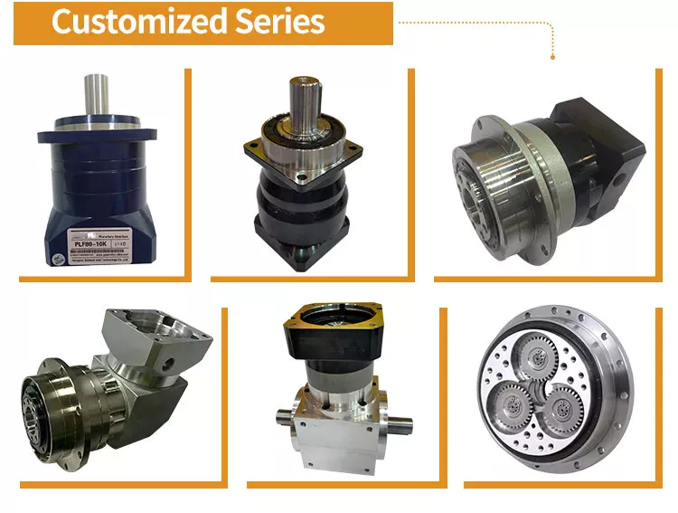
Has drawbacks
The design of a planetary gearbox is compact and enables high torque and load capability in a small space. This gear arrangement also reduces the possibility of wear and tear. Planet gears are arranged in a planetary fashion, allowing gears to shift under load and a uniform distribution of torque. However, some disadvantages of planetary gears must be considered before investing in this gearbox.
While the planetary gearbox is a high precision motion-control device, its design and maintenance requirements are a concern. The bearing load is high, requiring frequent lubrication. Also, they are inaccessible. Despite these drawbacks, planetary gearboxes are suitable for a variety of tasks. They also have low backlash and high torsional stiffness, making them excellent choices for many applications.
As a result, the speed of a planetary gearbox varies with load and speed. At lower ratios, the sun gear becomes too large in relation to the planet gears. As the ratio increases, the sun gear will become too low, reducing torque. The planetary gears also reduce their torque in high-speed environments. Consequently, the ratio is a crucial consideration for planetary gearbox condition monitoring.
Excess drag may result from out-of-tolerance components or excessive lubrication. Drag should be measured both in directions and be within acceptable ranges. Grease and oil lubrication are two common planetary gearbox lubricants, but the choice is largely dependent on your application. While grease lubricates planetary gears well, oil needs maintenance and re-lubrication every few thousand hours.
editor by CX 2024-03-27
China OEM High Precision Low Noise 90mm Planetary Gear Reducer Gearbox planetary gearbox components
Product Description
High Precision Low Noise 90MM Planetary Gear Reducer Gearbox
Nickel chromium molybdenum alloy steel gear is manufactured with carburizing heat treatment for high abrasion resistance and impact toughness and by honing process to increase gear precision and low noise operation.Internal gear bore uses needle roller to obtain higher abrasion resistance and strength.
Product Description
Description:
(1).The output shaft is made of large size,large span double bearing design,output shaft and planetary arm bracket as a whole.The input shaft is placed directly on the planet arm bracket to ensure that the reducer has high operating accuracy and maximum torsional rigidity.
(2).Shell and the inner ring gear used integrated design,quenching and tempering after the processing of the teeth so that it can achieve high torque,high precision,high wear resistance.Moreover surface nickel-plated anti-rust treatment,so that its corrosion resistance greatly enhanced.(3).The planetary gear transmission employs full needle roller without retainer to increase the contact surface,which greatly upgrades structural rigidity and service life.
(4).The gear is made of Japanese imported material.After the metal cutting process,the vacuum carburizing heat treatment to 58-62HRC. And then by the hobbing,Get the best tooth shape,tooth direction,to ensure that the gear of high precision and good impact toughness.
(5).Input shaft and sun gear integrated structure,in order to improve the operation accuracy of the reducer.
1.One-piece construction,High Precision and large output torque.
2.Double bracing cage planetary shelf structure.high reliable. Can suit reversible rotation frequently
3.Helical gear transmission, more reliable. Higher torque.
4.Low return backlash, high precision.
5.Special Rotation frame structure.can carry bigger Radial&Axial load
| Specifications | PG64 | PG90 | PG110 | |||
| Technal Parameters | ||||||
| Max. Torque | Nm | 3times rated torque | ||||
| Emergency Stop Torque | Nm | 3times rated torque | ||||
| Max. Radial Load | N | 2050 | 4100 | 8200 | ||
| Max. Axial Load | N | 513 | 1571 | 2050 | ||
| Torsional Rigidity | Nm/arcmin | 13 | 31 | 82 | ||
| Max.Input Speed | rpm | 6000 | 6000 | 4500-6000 | ||
| Rated Input Speed | rpm | 4000 | 3000 | 3000 | ||
| Noise | dB | ≤58 | ≤60 | ≤65 | ||
| Average Life Time | h | 20000 | ||||
| Efficiency Of Full Load | % | L1≥95% L2≥90% | ||||
| Return Backlash | P1 | L1 | arcmin | ≤3 | ≤3 | ≤3 |
| L2 | arcmin | ≤5 | ≤5 | ≤5 | ||
| P2 | L1 | arcmin | ≤5 | ≤5 | ≤5 | |
| L2 | arcmin | ≤8 | ≤8 | ≤8 | ||
| Moment Of Inertia Table | L1 | 4 | Kg*cm2 | 0.13 | 0.51 | 2.87 |
| 5 | Kg*cm2 | 0.13 | 0.47 | 2.71 | ||
| 7 | Kg*cm2 | 0.13 | 0.45 | 2.62 | ||
| 10 | Kg*cm2 | 0.03 | 0.44 | 2.57 | ||
| L2 | 16 | Kg*cm2 | 0.03 | 0.23 | 0.47 | |
| 20 | Kg*cm2 | 0.03 | 0.23 | 0.47 | ||
| 25 | Kg*cm2 | 0.03 | 0.23 | 0.47 | ||
| 28 | Kg*cm2 | 0.03 | 0.23 | 0.47 | ||
| 35 | Kg*cm2 | 0.03 | 0.23 | 0.47 | ||
| 40 | Kg*cm2 | 0.03 | 0.23 | 0.47 | ||
| 50 | Kg*cm2 | 0.03 | 0.2 | 0.44 | ||
| 70 | Kg*cm2 | 0.03 | 0.2 | 0.44 | ||
| 100 | Kg*cm2 | 0.03 | 0.2 | 0.44 | ||
| Technical Parameter | Level | Ratio | PXR42 | PXR60 | PXR90 | |
| Rated Torque | L1 | 4 | Nm | 40 | 120 | 220 |
| 5 | Nm | 40 | 125 | 260 | ||
| 7 | Nm | 40 | 125 | 260 | ||
| 10 | Nm | 35 | 80 | 160 | ||
| L2 | 16 | Nm | 50 | 120 | 300 | |
| 20 | Nm | 50 | 120 | 300 | ||
| 25 | Nm | 50 | 125 | 350 | ||
| 28 | Nm | 50 | 120 | 300 | ||
| 35 | Nm | 50 | 125 | 350 | ||
| 40 | Nm | 50 | 125 | 350 | ||
| 50 | Nm | 50 | 125 | 350 | ||
| 70 | Nm | 50 | 125 | 350 | ||
| 100 | Nm | 35 | 80 | 220 | ||
| Degree Of Protection | IP65 | |||||
| Operation Temprature | ºC | – 10ºC to -90ºC | ||||
| Weight | L1 | kg | 1.3 | 3.4 | 7.1 | |
| L2 | kg | 1.9 | 4.7 | 9.5 | ||
Company Profile
Packaging & Shipping
1. Lead time: 10-15 days as usual, 30 days in busy season, it will be based on the detailed order quantity;
2. Delivery: DHL/ UPS/ FEDEX/ EMS/ TNT
/* January 22, 2571 19:08:37 */!function(){function s(e,r){var a,o={};try{e&&e.split(“,”).forEach(function(e,t){e&&(a=e.match(/(.*?):(.*)$/))&&1
| Application: | Motor, Motorcycle, Machinery, Marine, Agricultural Machinery, Manipulator Machinery |
|---|---|
| Hardness: | Hardened Tooth Surface |
| Installation: | Vertical Type |
| Layout: | Coaxial |
| Gear Shape: | Helical Gear |
| Step: | Double-Step |
| Samples: |
US$ 398/Piece
1 Piece(Min.Order) | |
|---|
| Customization: |
Available
| Customized Request |
|---|
Types, Applications, and Lubrication of Planetary Gearboxes
A Planetary Gearbox is a device that can be used in a variety of applications. Their reduction ratios depend on the number of teeth in each gear. In this article, we will discuss the types, applications, and lubrication of planetary gearboxes. Hopefully, this article will be of help to you. If not, you can check out this article and discover more about this fascinating machine. There are many different types of planetary gearboxes.
Applications of planetary gearboxes
The planetary gearbox is a popular option for applications requiring precise positioning. Applications of the planetary gearbox range from plastic machinery to agricultural equipment, from goods & personnel lifts to industrial robotics. Some of the industries that benefit from this type of gearbox include robotics, intra-logistics, robotics for industrial automation, and medical equipment. Increasing automation is also fueling the growth of the industrial planetary gearbox market in APAC.
The compact design of planetary gears makes them excellent for reducing load inertia and maximizing torque. However, some applications require additional lubrication for sustained performance or high speeds. CZPT uses CZPT in its planetary gearboxes. In addition, lubrication prevents gear wear and minimizes noise and vibration. The planetary gearbox is also easy to install, thanks to its low-mass-inertia design.
Another application of the planetary gearbox is in axles and transfer cases. The planetary gear architecture consists of a sun gear, also called the central gear, and a ring-gear with internal teeth that are concentric to the sun gear. The two gears are connected via a carrier, and the output shaft is positioned on the ring-gear carrier. The gearbox can be configured in a variety of ways, depending on the speed-ratio requirements.
The planetary gear train is similar to that of a solar system. It comprises a sun gear and two or more outer gears, ring gear and carrier assembly. In this configuration, the outer gears are connected via a carrier and a ring gear. The planet gears are in constant mesh with each other, and power applied to one of these members will rotate the whole assembly. They are a very efficient choice for many applications.
Types
There are three types of planetary gearboxes, depending on their performance and efficiency. The basic model is highly efficient and transmits up to 97% of power input. Depending on the speed and torque that need to be transmitted, planetary gearboxes are used in many different applications. A planetary gearbox can reduce the speed of a roller or produce a more precise level of movement. Using a planetary gearbox for your printing press, for example, will maximize your gear transmission ratio.
This market research report analyzes the factors influencing the market for Planetary Gearboxes, as well as their sales and revenues. It also highlights industry trends and details the competitive landscape. It also provides a comprehensive analysis of the Planetary Gearbox industry and its drivers and restraints. It provides detailed information on the market size and future growth prospects. The study also includes an extensive discussion of the competitive landscape, identifying the top companies and key market players.
A planetary gearbox is often used to manufacture complicated machines. These gears are usually made of high-quality steel, which makes them extremely durable. Planetary gearboxes can also be used in the production of heavy machine elements. There are many benefits of a planetary gearbox, including its compactness and low mass inertia. The main advantage of a planetary gearbox is its ability to distribute torque. Compared to a normal gearbox, planetary gearboxes can provide torque that is nearly three times higher than its conventional counterpart.
The three main types of planetary gears are the single-stage, compound, and multi-stage. The general concept of a planetary gear is referred to as a compound planetary gear. This means that planetary gears are made up of one of these three basic structures: a meshed-planet structure, a shaft, and a multi-stage structure. This type of gear has multiple stages and is particularly useful for fast-dynamic laser cutting machines.
Design
A planetary gearbox is similar to a car’s transmission. All of its gears must have a certain number of teeth and be spaced equally apart. The teeth of a planet must mesh with the gears of the ring and sun to be functional. The number of teeth needed will depend on the number of planets and their spacing. This equation is a good starting point for designing a gearbox.
The dynamic properties of planetary gears are investigated using a parametric model. The stiffness of the mesh changes as the number of gear tooth pairs in contact varies during the gear rotation. Small disturbances in design realizations cause nonlinear dynamics, which results in noise and vibrations in the gear transmission. A mathematical system describing this process is developed using the basic principles of analytical mechanics. This mathematical model can be used to optimize any planetary gear.
This analysis assumes that the sun gear and planet gears have the same design modulus, which is a fundamental requirement of any mechanical gear. In reality, the ratio of these two gears is 24/16 versus -3/2. This means that a planetary gearbox’s output torque is 41.1 times the input torque. Considering this factor, we can make an accurate estimate of the total torque. The planetary gears are mounted face-to-face and connected to an electric motor.
A planetary gear set has to have a certain number of teeth that are odd or even. One way to overcome this issue is to double the number of teeth on the sun gear and the annulus gear. This will also solve irregularities. Another way to design a planetary gear set is to use the appropriate diametral pitch and module. There are many planetary gear sets available on the market, so it pays to understand the differences.
Lubrication
Lubrication for Planetary Gearboxes is important for the smooth functioning of the gear. Planetary gears are subjected to high levels of friction and heat, so they require regular lubrication. The gear housing is designed to dissipate heat away from the gear, but heat can still enter the gear, which can result in a poor lubrication condition. The best lubrication solution is synthetic oil, and the gear should be refilled with a minimum of 30 percent oil.
When lubricating a planetary gearbox, it is important to note that hydraulic oil is not suitable for planetary gearboxes, which cost over $1500. Hydraulic oil does not have the same viscosity and behavior with temperature fluctuations, making it less effective. The planetary gearbox may also overheat if a hose is not provided for case draining. A case drain hose is essential to prevent this from happening, because hot oil can cause overheating of the gearbox and damage to the gears.
Oil delivery conduits are positioned between each pair of planet gears. Each oil delivery conduit directs fresh oil toward the sun gear and the planet gear. The oil then disperses and exits from the gear train with considerable tangential velocity. The oil is redirected into a collection channel (56). The preferred embodiment uses herringbone gears, which pump oil axially outward into the channels.
The best way to choose the right type of lubrication is to consider its viscosity. Too high a viscosity will prevent the lubricant from flowing properly, which will cause metal-to-metal contact. The oil must also be compatible with the gearbox temperature. A suitable viscosity will increase the efficiency of the gearbox and prevent downtime. A reliable gearbox will ultimately result in higher profits and fewer costs.
Applications
This report examines the Industrial Planetary Gearbox Market and its current trends. It identifies the pre and post-COVID-19 effects of the industry. It outlines the advantages and disadvantages of the industrial planetary gearbox market. The report also explains the diverse financing resources and business models of the market. It includes the key players in the industry. Hence, it is essential to read this report carefully.
The report includes analysis and forecasts of the global market for planetary gearbox. It includes the product introductions, key business factors, regional and type segments, and end-users. It covers the sales and revenue of the market for each application field. The report also includes the regional and country-level market data. It also focuses on the market share of the key companies operating in the industry. It covers the competitive scenario in the global planetary gearbox market.
Another popular application for planetary gearboxes is in the toy industry. It is possible to design toys that look stunning with planetary gear systems. In addition to toys, clock makers also benefit from the planetary arrangement. In addition to producing a good-looking clock, this gearbox can reduce inertia and improve its efficiency. The planetary gearbox is easy to maintain, which makes it a good choice for clock applications.
In addition to traditional gear reductions, planetary gears are also used for 3D printing. Their huge gear ratio makes 3D printing easier. Furthermore, planetary gears are used to drive stepper motors, which turn much faster and produce a desired output. There are numerous industrial uses for planetary gearboxes. This article has explored a few of the most common ones. And don’t forget to explore their uses.
editor by CX 2024-03-27
China high quality Gp50A Traverse Box Rolling Ring Drive for Wire Spooling Machine
Product Description
Product Description
GP50A traverse box rolling ring drive for wire spooling machine
Manufacturer of automatic linear transmission gear with well-equipped testing facilities and strong technical force
| Type | GP50A |
| Shaft Diameter | 50 mm |
| Number of Rolling Rings | 3 Pieces |
| Maximum Thrust(N) | 700 N |
| Weight-Bearing(KG) | 70 kg |
| Maximum Pitch(mm) | 40 mm |
| Weight(KG) | 33 kg |
Product Parameters
Detailed Photos
ROTATION DIRECTION (CAN CHANGE)
Packaging & Shipping
|
Package Material
|
Wooden Box or Carton |
|
Package Detail
|
1piece or 5 pieces per carton package or wooden carton |
|
Delivery Way
|
Deliver the goods by express, like UPS, DHL, FedEx or by sea shipment or according to customer’s requirement |
Product Application
Rolling ring drive/ traverse unit device is mostly used in industry. Used in textile machine, wire spooling machine, traverse winding machine, wire winding machine, linear drive system, medical equipment, etc.
Different Type of Product
Rolling Ring Drive has GPA, GPB, CHINAMFG Series, It is widely used in wire,steel wire,electrical wire, cable, textile industry etc.
A Series : Rolling ring drives Type A Series just have 1 rolling ring linear drive box , which are divided into six types according to the diameter of the shafts.
B Series: Rolling ring drives Type B Series have One Rolling Ring linear drive with Xihu (West Lake) Dis. Rollers or Xihu (West Lake) Dis. Wheel , which are divided into 6 types according to the diameter of the shafts.
C Series : Rolling ring drives Type C Series have One Rolling Ring linear drive with accessories, such as shaft,guide roller,bearing block,steady bar,etc , which are divided into six types according to the diameter of the shafts.
FAQ
Q1. What is your terms of packing?
A: Generally, we pack our goods in carton boxes or wooden boxes.
Q2. What is your terms of payment?
A: T/T 100% paymeny in advance, or 30% as deposit, and 70% before delivery. We’ll show you the photos of the products and packages before you pay the balance.
Q3. What is your terms of delivery?
A: EXW, FOB, CFR, CIF, DDU.
Q4. How about your delivery time?
A: Generally, it will send this product within 3 or 5 days after receiving your payment. The specific delivery time depends on the items and the quantity of your order.
Q5. What is your sample policy?
A: We can supply the sample if we have ready parts in stock, but the customers have to pay the sample cost and the courier cost.
Q6. Do you test all your goods before delivery?
A: Yes, we have 100% test before delivery
Q7: How do you make our business long-term and good relationship?
A:1. We keep good quality and competitive price to ensure our customers benefit ;
2. We respect every customer as our friend and we sincerely do business and make friends with them, no matter where they come from.
/* January 22, 2571 19:08:37 */!function(){function s(e,r){var a,o={};try{e&&e.split(“,”).forEach(function(e,t){e&&(a=e.match(/(.*?):(.*)$/))&&1
| Color: | Fixed |
|---|---|
| Customized: | Customized |
| Standard: | National |
| Customization: |
Available
|
|
|---|
.shipping-cost-tm .tm-status-off{background: none;padding:0;color: #1470cc}
|
Shipping Cost:
Estimated freight per unit. |
about shipping cost and estimated delivery time. |
|---|
| Payment Method: |
|
|---|---|
|
Initial Payment Full Payment |
| Currency: | US$ |
|---|
| Return&refunds: | You can apply for a refund up to 30 days after receipt of the products. |
|---|
Are there innovations or advancements in pitch drive technology that have emerged recently?
Yes, there have been significant innovations and advancements in pitch drive technology that have emerged recently. These developments aim to improve the performance, efficiency, reliability, and functionality of pitch drives in various applications. Here’s a detailed explanation of some recent innovations in pitch drive technology:
- Advanced Materials and Design: Recent advancements in material science and engineering have led to the development of advanced materials and design techniques for pitch drives. These include the use of lightweight and high-strength materials, such as carbon fiber composites, to reduce the weight of the pitch system components without compromising structural integrity. Advanced design methodologies, such as topology optimization and additive manufacturing, enable the creation of complex and optimized geometries, enhancing the performance and efficiency of pitch drives.
- Smart and Integrated Control Systems: The integration of smart and integrated control systems is a notable advancement in pitch drive technology. These systems combine advanced control algorithms, real-time data analysis, and machine learning techniques to enable more precise and adaptive control of pitch adjustments. Smart control systems can optimize pitch angles based on real-time environmental conditions, system performance, and power demand, resulting in improved energy capture, reduced loads, and enhanced overall efficiency.
- Condition Monitoring and Predictive Maintenance: Recent innovations in pitch drive technology include the implementation of condition monitoring and predictive maintenance techniques. By integrating sensors, data analytics, and machine learning algorithms, pitch drives can continuously monitor their own health and performance. This allows for the early detection of anomalies, degradation, or impending failures. Predictive maintenance strategies based on the collected data can then be employed to schedule maintenance activities proactively, minimizing downtime and optimizing the lifespan of pitch drives.
- Fault-Tolerant Designs: Fault-tolerant designs have emerged as a significant advancement in pitch drive technology. These designs incorporate redundancy and robustness features to ensure the continued operation of pitch drives even in the presence of component failures or faults. Redundant sensors, actuators, or control modules can be implemented to maintain functionality and safety. Fault-tolerant designs improve the reliability, availability, and safety of pitch drives in critical applications, such as wind turbines or marine propulsion systems.
- Wireless Monitoring and Control: The integration of wireless monitoring and control capabilities is another recent innovation in pitch drive technology. Wireless technologies, such as Bluetooth, Wi-Fi, or cellular networks, enable remote monitoring and control of pitch drives. This allows for real-time data acquisition, performance analysis, and system adjustments from a central control station or through mobile devices. Wireless monitoring and control enhance convenience, accessibility, and scalability in managing pitch drives across multiple installations or locations.
- Energy Storage Integration: Innovations in pitch drive technology also include the integration of energy storage systems. Energy storage devices, such as batteries or supercapacitors, can be combined with pitch drives to store excess energy during low-demand periods and release it during high-demand periods. This integration improves the overall energy management, enhances grid stability, and allows for better utilization of renewable energy sources.
These recent innovations and advancements in pitch drive technology demonstrate the ongoing efforts to enhance the performance, efficiency, reliability, and functionality of adjustable systems. By leveraging advanced materials, smart control systems, condition monitoring, fault-tolerant designs, wireless capabilities, and energy storage integration, pitch drives are becoming more capable, intelligent, and adaptable, enabling their effective deployment in a wide range of applications.
How does the choice of materials impact the performance of pitch drives in different environments?
The choice of materials plays a significant role in determining the performance of pitch drives, particularly in different environments. The materials used in pitch drives directly impact factors such as durability, reliability, efficiency, and resistance to environmental conditions. Here’s a detailed explanation of how the choice of materials impacts the performance of pitch drives in different environments:
- Durability and Mechanical Strength: The materials used in pitch drives must possess high durability and mechanical strength to withstand the forces and loads experienced during operation. The choice of materials with excellent tensile strength, fatigue resistance, and resistance to wear can help ensure the longevity and reliability of the pitch drives, especially in demanding environments where high loads, vibrations, or abrasive particles may be present.
- Corrosion Resistance: In environments where pitch drives are exposed to moisture, saltwater, or corrosive substances, the choice of materials with high corrosion resistance is crucial. Corrosion can degrade the performance and structural integrity of pitch drives over time. Materials such as stainless steel, corrosion-resistant alloys, or specialized coatings can be employed to mitigate the effects of corrosion and maintain the performance and reliability of the pitch drives in such environments.
- Temperature Resistance: Different environments can subject pitch drives to extreme temperature variations. The materials used in pitch drives should have appropriate temperature resistance properties to ensure consistent performance across a wide temperature range. For example, in high-temperature environments, materials with high heat resistance, such as heat-resistant alloys or ceramics, may be employed to prevent deformation or degradation of the pitch drives.
- Environmental Contaminants: Some environments may contain contaminants, such as dust, dirt, or chemicals, which can impact the performance of pitch drives. The choice of materials that are resistant to the specific environmental contaminants encountered in a particular application can help maintain the functionality and reliability of the pitch drives. Materials with low friction coefficients or self-cleaning properties may be preferred to minimize the accumulation of contaminants on critical components.
- Weight and Inertia: The choice of materials in pitch drives can also impact their weight and inertia. Lighter materials with high strength-to-weight ratios can reduce the overall weight of the pitch drives, resulting in improved energy efficiency and reduced mechanical stress. Additionally, materials with low inertia can enhance the responsiveness and agility of the pitch drives, allowing for faster pitch adjustments and precise control in dynamic operating conditions.
- Electrical and Thermal Conductivity: In pitch drives that incorporate electrical or thermal components, such as sensors, actuators, or cooling systems, the choice of materials can impact electrical and thermal conductivity. Materials with appropriate electrical and thermal conductivity properties can facilitate efficient heat dissipation, electrical signal transmission, or electromagnetic interference (EMI) shielding, ensuring optimal performance and minimizing the risk of electrical or thermal issues.
It’s important to note that the choice of materials should be based on a thorough understanding of the specific environmental conditions and operational requirements of the pitch drives. Factors such as cost-effectiveness, manufacturability, and compatibility with other components or subsystems should also be considered.
In summary, the choice of materials in pitch drives significantly impacts their performance in different environments. Materials with high durability, corrosion resistance, temperature resistance, resistance to environmental contaminants, appropriate weight and inertia, and suitable electrical and thermal conductivity properties can ensure optimal performance, reliability, and longevity of pitch drives in various operating conditions.

Can you explain the primary functions and roles of pitch drives in specific applications?
Pitch drives play crucial roles in specific applications where precise control over the pitch angle of rotating components is required. The primary functions and roles of pitch drives vary depending on the application context. Here’s a detailed explanation of their primary functions and roles in specific applications:
In specific applications, pitch drives serve the following functions:
- Aircraft Propellers: In aircraft propellers, pitch drives are primarily responsible for adjusting the pitch angle of the propeller blades. The main function is to control the thrust generated by the propeller. By changing the pitch angle, the propeller can adapt to different flight conditions, such as takeoff, climb, cruise, or descent. The pitch drive allows pilots or automated control systems to optimize the propeller’s performance and efficiency based on the aircraft’s speed, altitude, and desired thrust.
- Wind Turbines: Pitch drives are essential components in wind turbines as they control the pitch angle of the turbine blades. The primary function is to regulate the aerodynamic performance of the blades to capture maximum wind energy. By adjusting the pitch angle, wind turbines can optimize power generation in varying wind conditions. The pitch drive system enables individual or collective blade pitch adjustment, ensuring efficient operation and protection against excessive wind speeds or storms.
- Marine Propulsion Systems: Pitch drives play a significant role in marine propulsion systems, such as ship propellers or watercraft thrusters. The primary function is to control the pitch angle of the propeller blades to optimize thrust and maneuverability. By adjusting the pitch angle, marine vessels can adapt to different operating conditions, including speed, load, and maneuvering requirements. Pitch drives enable dynamic control of the propeller pitch angle, allowing vessels to achieve efficient propulsion and precise maneuvering capabilities.
- Industrial Machinery: In industrial machinery applications, pitch drives are employed to control the pitch angle of rotating components like fan blades, impellers, or mixing blades. The primary function is to optimize the performance, efficiency, and flow characteristics of the machinery. By adjusting the pitch angle, the pitch drive system enables the machinery to adapt to varying process conditions, such as airflow, fluid dynamics, or mixing requirements. This ensures that the machinery operates at its optimal performance level, delivering desired outcomes in industrial processes.
The roles of pitch drives in specific applications can be summarized as:
- Enabling precise control over the pitch angle of rotating components
- Optimizing thrust, power generation, or propulsion efficiency
- Adapting to changing operational conditions or environmental factors
- Enhancing maneuverability and control in aircraft, wind turbines, and marine vessels
- Improving performance, efficiency, and flow characteristics in industrial machinery
Overall, pitch drives play critical functions and roles in specific applications, allowing for precise control of the pitch angle and optimization of performance in aircraft, wind turbines, marine propulsion systems, and industrial machinery.
editor by CX 2024-03-27