Product Description
Starshine Drive Cycloid Geared Motor Characteristics
1. Features:
1. Smooth running,low noise gear tooth needle more engagement.
2. Cycloidal tooth profile provides a high contact ratio to withstand overload shocks
3. Compact size: single ratio available from 1/9 to 1/87, double stage up from 1/99 to 1/7569
4. Ideal for dynamic applications: frequent start-stop-reversing duties suits for cyclo speed reducer since inertia is low
5. Reduce maintenance costs: high reliability, long life, minimal maintenance compared to conventional gearboxes
6. Internal parts replaceable with other brands to ensure running.
7. Grease Lubricated & Oil Lubricated Models Available
8. Output Shaft Rotation Direction: Single Reduction: Clockwise Rotation; Double Reduction→ Counter Clockwise Rotation
9. Ambient Conditions: Indoor Installation:10-40 Celsius, Max 85% Humidity, Under 1000m Altitude, Well Ventilated Environment, Free of corrosive, explosive gases, vapors and dust
10.Slow Speed Shaft Direction: Horizontal, Vertical Up & Down, Universal Direction
11.Mounting Style: Foot Mount, Flange Mount & Vertical F-flange Mount,
12. Input Connection: Cyclo Integral Motor, Hollow Input Shaft Adapter
13. Coupling Method With Driven Machine: Coupling, Gears, Chain Sprocket Or Belt
14. Cycloid reducer Capacity Range: 0.37kW ~ 11kW;
2. Technical parameters
| Type | Old Type | Output Torque | Output Shaft Dia. |
| SXJ00 | JXJ00 | 98N.m | φ30 |
| SXJ01 | JXJ01 | 221N.m | φ35 |
| SXJ02 | JXJ02 | 448N.m | φ45 |
| SXJ03 | JXJ03 | 986N.m | φ55 |
| SXJ04 | JXJ04 | 1504N.m | φ70 |
| SXJ05 | JXJ05 | 3051N.m | φ90 |
| SXJ06 | JXJ06 | 5608N.m | φ100 |
About Us
ZheJiang CZPT Drive Co.,Ltd,the predecessor was a state-owned military mould enterprise, was established in 1965. CZPT specializes in the complete power transmission solution for high-end equipment manufacturing industries based on the aim of “Platform Product, Application Design and Professional Service”.
CZPT have a strong technical force with over 350 employees at present, including over 30 engineering technicians, 30 quality inspectors, covering an area of 80000 square CZPT and kinds of advanced processing machines and testing equipments. We have a good foundation for the industry application development and service of high-end speed reducers & variators owning to the provincial engineering technology research center,the lab of gear speed reducers, and the base of modern R&D.
Our Team
Quality Control
Quality:Insist on Improvement,Strive for Excellence With the development of equipment manufacturing indurstry,customer never satirsfy with the current quality of our products,on the contrary,wcreate the value of quality.
Quality policy:to enhance the overall level in the field of power transmission
Quality View:Continuous Improvement , pursuit of excellence
Quality Philosophy:Quality creates value
3. Incoming Quality Control
To establish the AQL acceptable level of incoming material control, to provide the material for the whole inspection, sampling, immunity. On the acceptance of qualified products to warehousing, substandard goods to take return, check, rework, rework inspection; responsible for tracking bad, to monitor the supplier to take corrective
measures to prevent recurrence.
4. Process Quality Control
The manufacturing site of the first examination, inspection and final inspection, sampling according to the requirements of some projects, judging the quality change trend;
found abnormal phenomenon of manufacturing, and supervise the production department to improve, eliminate the abnormal phenomenon or state.
5. FQC(Final QC)
After the manufacturing department will complete the product, stand in the customer’s position on the finished product quality verification, in order to ensure the quality of
customer expectations and needs.
6. OQC(Outgoing QC)
After the product sample inspection to determine the qualified, allowing storage, but when the finished product from the warehouse before the formal delivery of the goods, there is a check, this is called the shipment inspection.Check content:In the warehouse storage and transfer status to confirm, while confirming the delivery of the
product is a product inspection to determine the qualified products.
7. Certification.
Packing
Delivery
/* January 22, 2571 19:08:37 */!function(){function s(e,r){var a,o={};try{e&&e.split(“,”).forEach(function(e,t){e&&(a=e.match(/(.*?):(.*)$/))&&1
| Application: | Motor, Machinery, Agricultural Machinery, Ceramic, Glass, Logistic |
|---|---|
| Hardness: | Hardened Tooth Surface |
| Installation: | Horizontal Type |
| Layout: | Coaxial |
| Gear Shape: | Cylindrical Gear |
| Step: | Single-Step |
| Customization: |
Available
| Customized Request |
|---|

What is a Planetary Gearbox?
A planetary gearbox is a mechanical device in which the teeth of a planet mesh with the teeth of its sun or ring. The number of teeth and the spacing of planets will determine whether the teeth mesh correctly. In this article, we will learn more about planetary gearboxes. Besides understanding their working, you can also learn how to design your own. Here are some examples:
planetary gearboxes
If your car has an automatic transmission, then a planetary gearbox is the type you have. It is possible to find out if you have this type of gearbox by consulting the owner’s manual, calling the service department of your car’s manufacturer, or conducting a search using your favorite search engine. However, planetary gears are more complex and have many more components than standard gearboxes. The following information will explain more about this type of gearbox.
Planetary gearboxes use three different gear types to transmit torque. The sun gear sits in the center of the gear assembly, while the other gears rotate around it. A carrier connects the two gears, and is designed to set the spacing between them. When the gears are rotated, the carrier will spin, enabling the entire assembly to work together. The carrier also incorporates the output shaft. For this gearbox to work effectively, it must meet the application’s requirements.
There are three main types of planetary gearboxes: the basic model is highly efficient and transmits 97% of the power input. The earliest models are not complex, but they do have some key differences. Some of these differences make them ideal for various applications. For example, a planetary gearbox can operate in alternating and continuous operation, with the output support having internal grooving. Some designs have more than one output shaft, allowing the user to choose the configuration and torque that is best for their application.
One of the main differences between a planetary gearbox and a conventional one is the way the planetary parts move. A planetary gearbox may have multiple axes for increased torque. A planetary gearbox can provide a torque up to 113,000 N.m. by rotating its maximum teeth simultaneously. They are the ideal choice for space-constrained applications. For instance, a car with small spaces can install one with ease.
A planetary gearbox’s gear ratio is determined by the ratio of the sun gear to the ring gear. The number of teeth on the sun gear is a way to adjust the gear ratio. Smaller sun gears result in larger planetary gear ratios, while larger ones cause a decrease in torque. The ratio between planetary gears ranges from 3:1 to 10:1, with the lowest ratio being three. The greatest possible ratio is 10:1.
A planetary gearbox has many benefits. The compact design makes them a more efficient choice for small motors and is advantageous for servo functions. Planetary gearboxes have low inertia, which is an important factor, especially in servo applications, since the inertia of the gearbox adds to the motor’s load inertia. The planetary gearboxes are typically lubricated with grease or oil, so you don’t need to worry about re-lubrication or maintenance.
planetary gearboxes with output shaft
The advantages of planetary gearboxes are numerous. They are widely used in many applications, from automobiles to medical equipment, goods & personnel lifts to machine tools. They are also used in derrick & dockyard cranes and slewing drives. These gearboxes are available in various sizes and shapes, ranging from small to extremely large. There are many different types, and each is designed to suit its intended use.
The LP generation 3 gearhead series combines maximum quality with economic precision in a low-backlash planetary gearbox. The output shaft version is especially suited for high-speed, highly dynamic cyclic operation. Another version is the SP+ HIGH SPEED. The SP+ high-speed version is designed to achieve maximum speeds while in continuous operation. If you need a planetary gearbox with an output shaft, look no further. It is the best choice for many applications.
As the name suggests, a planetary gearbox incorporates planetary parts and an output shaft. The outer gears (also called the planetary gears) are connected by a carrier to the output shaft. The carrier is then connected to the output shaft by a ring. There are two or more planetary gears inside the planetary gearbox. Each gear is connected to a carrier, which is connected to the output shaft.
An epicyclic planetary gear train can be assembled so that the planet gear rolls around the sun gear. In the wheel drive planetary gearbox, the planetary gears are grouped over the housing to optimize the size and weight of the system. The planetary gear train can handle torques as high as 332,000 N.m., with the ring gear being fixed while the sun gear is movable.
Another advantage of a planetary gearbox is that it uses many teeth at once. This allows for high speed reduction and high torque transmission, and it is extremely compact. Planetary gearboxes with output shaft are ideal for space-constrained applications. Their compact size and minimal weight make them a popular choice in many industries. They are also known as epicyclic gears and are used in many different types of machines.
A planetary gearbox can have three components. A central sun gear, an outer ring known as the inner gear, and an output shaft. These three components are linked by a carrier. The carrier rotates so that the input and output gears are in sync. They also have a standard gap between the gears. The carrier also acts as the output shaft. They can be used to create small machines, such as a bicycle acceleration hub.
planetary gearboxes with integer number of teeth
When designing a planetary gearbox, one must determine the amount of tooth count. This figure is known as the mesh load factor Kg, and is based on the normal tooth forces that are generated in each mesh. The number of planets, the error in the gear design, and the rigidity of the housing all affect Kg. Depending on the type of application, Kg can be calculated by using different standards.
In a typical planetary gearbox, the ratio is an integer number, and the lowest is 3:1. At a ratio of 10, the sun gear is too large and the sun wheel is too low to provide a sufficient amount of torque. In most cases, the ratio is an integer value, and the teeth are evenly spaced. The gear mesh is then balanced to grade 2. The carrier is measured three-dimensionally to detect the accuracy of the planet pin hole in the carrier.
In the simplest case, each planetary gear mesh produces a dynamic signal at its mesh frequency. These signals can cancel or reinforce in various ways. A helix angle, however, introduces axial forces into the gear mesh, which can be cancelled or reinforced in the same way as torques. As the helix angle is an integer number, this planetary gear model does not necessarily require infinite precision.
The resulting motion period is measured in rotational angles. This figure can be used to determine fault diagnosis and calculate the minimum data length required. It can also be used to calculate the kinematic motion of a faulty planet gear tooth. It is important to note that fault-mesh motion is not instantaneous, and therefore, it requires a sufficient amount of time to fully mesh a faulty planet gear.
The load-share factor is similar to that of spur and helical gearboxes, and can be used to calculate dynamic load sharing. When the load share factor is low, the individual gear meshes are slightly loaded. Deflections can vary, especially with high-precision gears. Therefore, the design process should incorporate the tolerance chain. This will ensure the correct ratio of gear mesh.
A planetary gearbox is a type of planetary gear system that is used in motors. It has a sun gear at the center and a set of outer gears. Each gear turns according to its axis around the sun. They are interconnected by a ring component and are connected to each other through a carrier. The carrier also includes the output shaft. And since the sun gear is centered, the mesh is standard.
As an added benefit, planetary gearboxes have sliding surfaces, which reduce noise and vibration. Despite the high-quality of planetary gearboxes, it is important to properly lubricate them to avoid wear and tear. CZPT uses CZPT. In order to make the planetary gearboxes last a long time, the lubricant is usually incorporated in the planetary gearbox.


editor by Dream 2024-04-29
China factory Planetary Gearbox of CZPT Supplier 8-12t Road Roller Travel&Wheel Drives design of planetary gearbox
Product Description
Elite GFT Travel Drives are unsurpassed by any crawler or milling machines. Thanks to compact, rugged design, high torque and load capabilities, and optional mechanical lifetime seals, these solutions are the best possible option for the machine. All units are available with a fail-safe parking brake and most have the option of cartridge type fixed or variable systems.
Features:
Compact structure and space-saving design
Robust main bearing system
High torque capacity
High load capacity
Integrated static multiple disk parking brake
Optional Disconnect device for towing
Optional Quick disconnection device
Simple mounting
Easy oil change
Low-noise running operation
Specifications:
| Model | HFT571T |
| Max. output torque: | 20000 N.m |
| Input speed |
up to 4,000 rpm |
| Ratio: | 2-stage: 17, 20, 22, 27, 32, 38, 46, 50, 54 2-stage:78,88,90,102,120,140,153,170,227 |
| Brake options |
Hydraulically released parking brake on request |
| Dynamic Loading: | 232KN |
| Static Loading: | 420 KN |
| Applicable motors: | Cartridge axial piston hydraulic motors Flanged axial piston hydraulic motors Hydraulic orbit motors Electrical motors
|
| Application: | Travel for Track, Chain and Wheel driving machines |
In conclusion, ELITE Hydraulic offers quality, value, and professional power transmission solutions that cater to a wide variety of industries. With their expertise, experience, and commitment to customer satisfaction, you can be sure that you’re in safe hands when working with them. Whether you need travel gearbox, electrical drive, travel drive,slew gearbox,winche gearbox,cutter gearbox,truck mixer gearbox,twin shaft mixer or other hydraulic transmission solutions, you can trust ELITE Hydraulic to provide you with the best possible solutions. Contact them today to learn more about their power transmission products and services.
/* January 22, 2571 19:08:37 */!function(){function s(e,r){var a,o={};try{e&&e.split(“,”).forEach(function(e,t){e&&(a=e.match(/(.*?):(.*)$/))&&1
| Application: | Motor, Motorcycle, Machinery, Agricultural Machinery |
|---|---|
| Function: | Change Drive Torque, Speed Changing, Speed Reduction |
| Hardness: | Hardened Tooth Surface |
| Step: | Three-Step |
| Type: | Planetary Gear Box |
| Input Speed: | 4000rpm |
| Customization: |
Available
| Customized Request |
|---|
Planetary Gearbox Advantages and Disadvantages
A planetary gearbox is a type of mechanical drive with a single output shaft. They are suitable for both clockwise and counterclockwise rotations, have less inertia, and operate at higher speeds. Here are some advantages and disadvantages of this type of gearbox. Let us see what these advantages are and why you should use them in your applications. Listed below are some of the benefits of planetary gearboxes.
Suitable for counterclockwise and clockwise rotation
If you want to teach children about the clock hands, you can buy some resources for counterclockwise and asymmetrical rotation. These resources include worksheets for identifying degrees of rotation, writing rules for rotation, and visual processing. You can also use these resources to teach angles. For example, the translation of shapes activity pack helps children learn about the rotation of geometric shapes. Similarly, the visual perception activity sheet helps children understand how to process information visually.
Various studies have been done to understand the anatomical substrate of rotations. In a recent study, CZPT et al. compared the position of the transitional zone electrocardiographically and anatomically. The authors found that the transitional zone was normal in nine of 33 subjects, indicating that rotation is not a sign of disease. Similarly, a counterclockwise rotation may be caused by a genetic or environmental factor.
The core tip data should be designed to work in both clockwise and counterclockwise rotation. Counterclockwise rotation requires a different starting point than a clockwise rotation. In North America, star-delta starting is used. In both cases, the figure is rotated about its point. Counterclockwise rotation, on the other hand, is done in the opposite direction. In addition, it is possible to create counterclockwise rotation using the same gimbal.
Despite its name, both clockwise and counterclockwise rotation requires a certain amount of force to rotate. When rotating clockwise, the object faces upwards. Counterclockwise rotation, on the other hand, starts from the top position and heads to the right. If rotating in the opposite direction, the object turns counterclockwise, and vice versa. The clockwise movement, in contrast, is the reverse of counterclockwise rotation.
Has less inertia
The primary difference between a planetary gearbox and a normal pinion-and-gear reducer is the ratio. A planetary gearbox will produce less inertia, which is an important advantage because it will reduce torque and energy requirements. The ratio of the planetary gearbox to its fixed axis counterpart is a factor of three. A planetary gearbox has smaller gears than a conventional planetary, so its inertia is proportional to the number of planets.
Planetary gears are less inertia than spur gears, and they share the load across multiple gear teeth. This means that they will have low backlash, and this is essential for applications with high start-stop cycles and frequent rotational direction changes. Another benefit is the high stiffness. A planetary gearbox will have less backlash than a spur gearbox, which means that it will be more reliable.
A planetary gearbox can use either spur or helical gears. The former provides higher torque ratings while the latter has less noise and stiffness. Both types of gears are useful in motorsports, aerospace, truck transmissions, and power generation units. They require more assembly time than a conventional parallel shaft gear, but the PD series is the more efficient alternative. PD series planetary gears are suitable for many applications, including servo and robotics.
In contrast, a planetary gear set can have varying input speed. This can affect the frequency response of the gearset. A mathematical model of the two-stage planetary gears has non-stationary effects and correlates with experimental findings. Fig. 6.3 shows an addendum. The dedendum’s minimum value is approximately 1.25m. When the dedendum is at its smallest, the dedendum has less inertia.
Offers greater reliability
The Planetary Gearbox is a better option for driving a vehicle than a standard spur gearbox. A planetary gearbox is less expensive, and they have better backlash, higher load capacity, and greater shock loads. Unlike spur gearboxes, however, mechanical noise is virtually nonexistent. This makes them more reliable in high-shock situations, as well as in a wide range of applications.
The Economy Series has the same power density and torque capacity of the Precision Helical Series, but it lacks the precision of the latter. In contrast, Economy Series planetary gearboxes feature straight spur planetary gearing, and they are used in applications requiring high torque. Both types of gearboxes are compatible with NEMA servo motors. If torque density is important, a planetary gearbox is the best choice.
The Dispersion of External Load: The SSI model has been extensively used to model the reliability of planetary gear systems. This model takes the contact force and fatigue strength of the system as generalized stress and strength. It also provides a theoretical framework to evaluate the reliability of planetary gear systems. It also has many other advantages that make it the preferred choice for high-stress applications. The Planetary Gearbox offers greater reliability and efficiency than traditional rack and pinion gear systems.
Planetary gearing has greater reliability and compact design. Its compact design allows for wider applications with concerns about space and weight. Additionally, the increased torque and reduction makes planetary gearboxes an excellent choice for a wide variety of applications. There are three major types of planetary gearboxes, each with its own advantages. This article describes a few of them. Once you understand their workings, you will be able to choose the best planetary gearbox for your needs.
Has higher operating speeds
When you look at planetary gearboxes, you might be confused about which one to choose. The primary issue is the application of the gearbox. You must also decide on secondary factors like noise level, corrosion resistance, construction, price, and availability worldwide. Some constructors work faster than others and deliver the gearboxes on the same day. However, the latter ones often deliver the planetary gearbox out of stock.
Compared to conventional gearboxes, a planetary gearbox can run at higher speeds when the input speed fluctuates. However, these gears are not very efficient in high-speed applications because of their increased noise levels. This makes planetary gears unsuitable for applications involving a great deal of noise. That is why most planetary gears are used in small-scale applications. There are some exceptions, but in general, a planetary gearbox is better suited for applications with higher operating speeds.
The basic planetary gearbox is a compact alternative to normal pinion-and-gear reducers. They can be used in a wide variety of applications where space and weight are concerns. Its efficiency is also higher, delivering 97% of the power input. It comes in three different types based on the performance. A planetary gearbox can also be classified as a worm gear, a spur gear, or a sprocket.
A planetary gearhead has a high-precision design and can generate substantial torque for their size. It also reduces backlash to two arc-min. Additionally, it is lubricated for life, which means no maintenance is needed. It can fit into a small machine envelope and has a small footprint. Moreover, the helical crowned gearing provides fast positioning. A sealed gearbox prevents abrasive dust from getting into the planetary gearhead.
Has drawbacks
The design of a planetary gearbox is compact and enables high torque and load capability in a small space. This gear arrangement also reduces the possibility of wear and tear. Planet gears are arranged in a planetary fashion, allowing gears to shift under load and a uniform distribution of torque. However, some disadvantages of planetary gears must be considered before investing in this gearbox.
While the planetary gearbox is a high precision motion-control device, its design and maintenance requirements are a concern. The bearing load is high, requiring frequent lubrication. Also, they are inaccessible. Despite these drawbacks, planetary gearboxes are suitable for a variety of tasks. They also have low backlash and high torsional stiffness, making them excellent choices for many applications.
As a result, the speed of a planetary gearbox varies with load and speed. At lower ratios, the sun gear becomes too large in relation to the planet gears. As the ratio increases, the sun gear will become too low, reducing torque. The planetary gears also reduce their torque in high-speed environments. Consequently, the ratio is a crucial consideration for planetary gearbox condition monitoring.
Excess drag may result from out-of-tolerance components or excessive lubrication. Drag should be measured both in directions and be within acceptable ranges. Grease and oil lubrication are two common planetary gearbox lubricants, but the choice is largely dependent on your application. While grease lubricates planetary gears well, oil needs maintenance and re-lubrication every few thousand hours.
editor by Dream 2024-04-29
China Custom Precision Encoder 60 Flange Servo Motor for Reliable Performance
Product Description
Product Description
Company Profile
FAQ
| Q:How to choose a multi-degree-of-freedom motion platform? A: First, clarify the type of platform needed (degrees of freedom, simulation platform, positioning platform, swing platform, vibration platform, etc.). Next, determine the platform’s payload, followed by size requirements, and finally, specify the platform’s attitude data. Q:What is the repeatability of a multi-degree-of-freedom motion platform? Q:What is the resolution of a multi-degree-of-freedom motion platform? Q:Does a multi-degree-of-freedom motion platform require maintenance? How to maintain it? Q:What is the maximum effective load that a multi-degree-of-freedom motion platform can handle? Q:What is the maximum angular position that a multi-degree-of-freedom motion platform can achieve? |
/* January 22, 2571 19:08:37 */!function(){function s(e,r){var a,o={};try{e&&e.split(“,”).forEach(function(e,t){e&&(a=e.match(/(.*?):(.*)$/))&&1
| Application: | Industrial |
|---|---|
| Speed: | High Speed |
| Number of Stator: | Single-Phase |
| Function: | Driving, Control |
| Certification: | ISO9001 |
| Motor: | Servo Motor |
| Customization: |
Available
|
|
|---|

How does the choice of pitch drives affect the overall performance and reliability of adjustable systems?
The choice of pitch drives has a significant impact on the overall performance and reliability of adjustable systems. Here’s a detailed explanation of how the choice of pitch drives affects these aspects:
- Performance:
The performance of adjustable systems, such as wind turbines or rotor blades, depends on the effectiveness and responsiveness of the pitch control mechanism. The choice of pitch drives directly influences the system’s ability to adjust the pitch angles accurately, quickly, and precisely. Several factors contribute to the performance impact:
- Speed and Responsiveness: The speed at which pitch drives can adjust the pitch angles affects the system’s ability to optimize performance in changing wind conditions. High-performance pitch drives with fast response times enable quicker and more precise adjustments, allowing the system to capture more energy from the wind and maintain optimal operating conditions.
- Control Accuracy: The accuracy of pitch angle control is crucial for maintaining the desired power output, load distribution, and overall system stability. The choice of pitch drives with precise control mechanisms ensures that the adjustable components accurately follow the control commands, minimizing deviations from the desired pitch angles and maximizing energy capture.
- Dynamic Performance: Adjustable systems often experience dynamic loads and varying wind conditions. The choice of pitch drives with robust dynamic performance characteristics, such as high torque capacity and low inertia, allows the system to effectively respond to dynamic loads, maintain stability, and optimize power generation.
- Reliability:
The reliability of adjustable systems is heavily influenced by the choice of pitch drives. The reliability aspect encompasses the system’s ability to operate consistently, withstand environmental conditions, and minimize the risk of failures or malfunctions. The choice of pitch drives impacts reliability in the following ways:
- Durability and Longevity: High-quality pitch drives designed for industrial applications provide durability and extended service life. They can withstand the operational stresses, environmental conditions, and mechanical loads associated with adjustable systems, reducing the likelihood of premature failures and the need for frequent replacements.
- Mechanical Integrity: The mechanical integrity of pitch drives, including the gears, bearings, and other moving components, is crucial for reliable operation. Choosing pitch drives from reputable manufacturers with a track record of reliable products ensures the use of robust and well-engineered components that can withstand continuous operation and minimize the risk of mechanical failures.
- Maintenance and Serviceability: The choice of pitch drives can influence the ease of maintenance and serviceability of adjustable systems. Well-designed pitch drives with accessible maintenance points, clear documentation, and available spare parts facilitate routine maintenance tasks, inspections, and repairs, reducing downtime and enhancing overall system reliability.
- Environmental Considerations: Adjustable systems often operate in challenging environmental conditions, such as high winds, temperature variations, and exposure to dust, moisture, or corrosive elements. The choice of pitch drives that are specifically designed and tested for such environments ensures resistance to environmental stresses, enhancing the reliability and longevity of the system.
In summary, the choice of pitch drives significantly affects the performance and reliability of adjustable systems. The selection of pitch drives with high-speed responsiveness, precise control accuracy, and robust dynamic performance optimizes the system’s performance in varying wind conditions. Additionally, choosing pitch drives with durability, mechanical integrity, ease of maintenance, and environmental suitability enhances the overall reliability of the system by minimizing the risk of failures, extending service life, and facilitating maintenance activities.

How do pitch drives contribute to precise and controlled pitch adjustments in machinery?
Pitch drives play a crucial role in achieving precise and controlled pitch adjustments in machinery. They provide the necessary actuation and control mechanisms to alter the pitch angle of rotating components, such as blades or propellers, with accuracy and reliability. Here’s a detailed explanation of how pitch drives contribute to precise and controlled pitch adjustments:
Pitch drives utilize various mechanisms, such as hydraulic, pneumatic, electric, or mechanical systems, to generate the required force or torque for pitch angle adjustments. These mechanisms are controlled through integrated control systems or external control signals, allowing for precise and controlled manipulation of the pitch angle. Here are the key ways in which pitch drives contribute to precise and controlled pitch adjustments:
- Accurate Positioning: Pitch drives offer the ability to accurately position the rotating components at the desired pitch angle. They allow for fine adjustments, enabling precise control over the orientation and alignment of the blades or propellers. This accuracy is essential in applications where optimal performance, efficiency, and aerodynamic characteristics are critical.
- Dynamic Control: Pitch drives enable dynamic control over the pitch angle, allowing for real-time adjustments based on changing conditions or operational requirements. With fast response times and precise control algorithms, pitch drives can adapt to varying loads, wind speeds, or other external factors, ensuring that the pitch angle is continuously optimized for optimal performance and safety.
- Load Distribution: In multi-blade systems, such as wind turbines or helicopter rotors, pitch drives contribute to precise and controlled pitch adjustments, resulting in optimized load distribution across the blades. By individually adjusting the pitch angle of each blade, pitch drives can distribute the load evenly, minimize aerodynamic imbalances, and enhance the overall efficiency and lifespan of the machinery.
- Safety and Protection: Pitch drives provide a means for safety and protection in machinery. They enable the adjustment of pitch angles to regulate the rotational speed, prevent over-speeding, and mitigate the effects of excessive loads or adverse operating conditions. By allowing controlled pitch adjustments, pitch drives contribute to safe and reliable operation, protecting the machinery from potential damage or catastrophic failures.
- Automation and Control Integration: Pitch drives can be integrated into automated control systems, allowing for seamless integration and coordination with other components or subsystems of the machinery. Through sensors, feedback loops, and control algorithms, pitch drives can be part of a closed-loop control system that continuously monitors and adjusts the pitch angle based on predefined parameters or operational objectives. This integration enhances the precision, responsiveness, and overall performance of pitch adjustments.
- Flexibility and Adaptability: Different types of pitch drives offer varying degrees of flexibility and adaptability. Electric pitch drives, for example, can offer programmable control algorithms, allowing for customized pitch adjustment profiles or adaptive control strategies. This flexibility enables the pitch drives to adapt to specific operating conditions, load variations, or performance requirements, ensuring precise and controlled pitch adjustments in diverse machinery applications.
Overall, pitch drives provide the necessary actuation and control mechanisms to achieve precise and controlled pitch adjustments in machinery. Through accurate positioning, dynamic control, load distribution, safety features, automation, and adaptability, pitch drives contribute to optimized performance, efficiency, and reliability in various industrial sectors.

Can you explain the primary functions and roles of pitch drives in specific applications?
Pitch drives play crucial roles in specific applications where precise control over the pitch angle of rotating components is required. The primary functions and roles of pitch drives vary depending on the application context. Here’s a detailed explanation of their primary functions and roles in specific applications:
In specific applications, pitch drives serve the following functions:
- Aircraft Propellers: In aircraft propellers, pitch drives are primarily responsible for adjusting the pitch angle of the propeller blades. The main function is to control the thrust generated by the propeller. By changing the pitch angle, the propeller can adapt to different flight conditions, such as takeoff, climb, cruise, or descent. The pitch drive allows pilots or automated control systems to optimize the propeller’s performance and efficiency based on the aircraft’s speed, altitude, and desired thrust.
- Wind Turbines: Pitch drives are essential components in wind turbines as they control the pitch angle of the turbine blades. The primary function is to regulate the aerodynamic performance of the blades to capture maximum wind energy. By adjusting the pitch angle, wind turbines can optimize power generation in varying wind conditions. The pitch drive system enables individual or collective blade pitch adjustment, ensuring efficient operation and protection against excessive wind speeds or storms.
- Marine Propulsion Systems: Pitch drives play a significant role in marine propulsion systems, such as ship propellers or watercraft thrusters. The primary function is to control the pitch angle of the propeller blades to optimize thrust and maneuverability. By adjusting the pitch angle, marine vessels can adapt to different operating conditions, including speed, load, and maneuvering requirements. Pitch drives enable dynamic control of the propeller pitch angle, allowing vessels to achieve efficient propulsion and precise maneuvering capabilities.
- Industrial Machinery: In industrial machinery applications, pitch drives are employed to control the pitch angle of rotating components like fan blades, impellers, or mixing blades. The primary function is to optimize the performance, efficiency, and flow characteristics of the machinery. By adjusting the pitch angle, the pitch drive system enables the machinery to adapt to varying process conditions, such as airflow, fluid dynamics, or mixing requirements. This ensures that the machinery operates at its optimal performance level, delivering desired outcomes in industrial processes.
The roles of pitch drives in specific applications can be summarized as:
- Enabling precise control over the pitch angle of rotating components
- Optimizing thrust, power generation, or propulsion efficiency
- Adapting to changing operational conditions or environmental factors
- Enhancing maneuverability and control in aircraft, wind turbines, and marine vessels
- Improving performance, efficiency, and flow characteristics in industrial machinery
Overall, pitch drives play critical functions and roles in specific applications, allowing for precise control of the pitch angle and optimization of performance in aircraft, wind turbines, marine propulsion systems, and industrial machinery.


editor by Dream 2024-04-29
China Standard Factory Direct Wire Winder Machine Spare Parts Gp30A Traverse Unit Drives
Product Description
Product Description
Factory direct wire winder machine spare parts GP30A traverse unit drives
Manufacturer of automatic linear transmission gear with well-equipped testing facilities and strong technical force
| Type | GP30A |
| Shaft Diameter | 30 mm |
| Number of Rolling Rings | 3 Pieces |
| Maximum Thrust(N) | 260 N |
| Weight-Bearing(KG) | 26 kg |
| Maximum Pitch(mm) | 25 mm |
| Weight(KG) | 3 kg |
Product Parameters
Detailed Photos
ROTATION DIRECTION (CAN CHANGE)
Packaging & Shipping
|
Package Material
|
Wooden Box or Carton |
|
Package Detail
|
1piece or 5 pieces per carton package or wooden carton |
|
Delivery Way
|
Deliver the goods by express, like UPS, DHL, FedEx or by sea shipment or according to customer’s requirement |
Product Application
Rolling ring drive/ traverse unit device is mostly used in industry. Used in textile machine, wire spooling machine, traverse winding machine, wire winding machine, linear drive system, medical equipment, etc.
Different Type of Product
Rolling Ring Drive has GPA, GPB, CHINAMFG Series, It is widely used in wire,steel wire,electrical wire, cable, textile industry etc.
A Series : Rolling ring drives Type A Series just have 1 rolling ring linear drive box , which are divided into six types according to the diameter of the shafts.
B Series: Rolling ring drives Type B Series have One Rolling Ring linear drive with Xihu (West Lake) Dis. Rollers or Xihu (West Lake) Dis. Wheel , which are divided into 6 types according to the diameter of the shafts.
C Series : Rolling ring drives Type C Series have One Rolling Ring linear drive with accessories, such as shaft,guide roller,bearing block,steady bar,etc , which are divided into six types according to the diameter of the shafts.
FAQ
Q1. What is your terms of packing?
A: Generally, we pack our goods in carton boxes or wooden boxes.
Q2. What is your terms of payment?
A: T/T 100% paymeny in advance, or 30% as deposit, and 70% before delivery. We’ll show you the photos of the products and packages before you pay the balance.
Q3. What is your terms of delivery?
A: EXW, FOB, CFR, CIF, DDU.
Q4. How about your delivery time?
A: Generally, it will send this product within 3 or 5 days after receiving your payment. The specific delivery time depends on the items and the quantity of your order.
Q5. What is your sample policy?
A: We can supply the sample if we have ready parts in stock, but the customers have to pay the sample cost and the courier cost.
Q6. Do you test all your goods before delivery?
A: Yes, we have 100% test before delivery
Q7: How do you make our business long-term and good relationship?
A:1. We keep good quality and competitive price to ensure our customers benefit ;
2. We respect every customer as our friend and we sincerely do business and make friends with them, no matter where they come from.
/* January 22, 2571 19:08:37 */!function(){function s(e,r){var a,o={};try{e&&e.split(“,”).forEach(function(e,t){e&&(a=e.match(/(.*?):(.*)$/))&&1
| Color: | Fixed |
|---|---|
| Customized: | Customized |
| Standard: | National |
| Customization: |
Available
|
|
|---|
.shipping-cost-tm .tm-status-off{background: none;padding:0;color: #1470cc}
|
Shipping Cost:
Estimated freight per unit. |
about shipping cost and estimated delivery time. |
|---|
| Payment Method: |
|
|---|---|
|
Initial Payment Full Payment |
| Currency: | US$ |
|---|
| Return&refunds: | You can apply for a refund up to 30 days after receipt of the products. |
|---|
How do pitch drives contribute to the adaptability and versatility of adjustable systems in various settings?
Pitch drives play a crucial role in enhancing the adaptability and versatility of adjustable systems across various settings. These drives enable precise control over the pitch angles of adjustable components, allowing them to respond dynamically to changing operating conditions. Here’s a detailed explanation of how pitch drives contribute to the adaptability and versatility of adjustable systems:
- Optimized Performance: By adjusting the pitch angles of blades, propellers, or other adjustable components, pitch drives optimize the performance of adjustable systems. In applications such as wind turbines or marine propulsion systems, pitch drives enable the system to capture maximum energy from the wind or water currents. By adjusting the pitch angles based on real-time conditions, such as wind speed or load demand, pitch drives ensure that the system operates at its peak performance, maximizing energy conversion, and overall efficiency.
- Load Control and Mitigation: Pitch drives provide load control capabilities, allowing adjustable systems to manage and mitigate excessive loads. By adjusting the pitch angles, the systems can redistribute the loads on components, reducing stress concentrations and minimizing the risk of fatigue or failure. This load control capability is particularly valuable in applications where adjustable systems operate under varying and unpredictable load conditions, such as wind turbines experiencing gusty winds or marine systems encountering wave-induced loads.
- Dynamic Response: The ability of pitch drives to adjust pitch angles in real-time enables adjustable systems to have a dynamic response to changing operating conditions. For example, in wind turbines, pitch drives can respond to sudden changes in wind speed or direction, allowing the blades to maintain optimal aerodynamic performance and prevent excessive loads. This dynamic response capability enhances the adaptability of adjustable systems, enabling them to quickly adjust and optimize their operation in response to environmental changes.
- Power Regulation: Pitch drives contribute to the adaptability of adjustable systems by enabling power regulation. By adjusting the pitch angles, the systems can control the power output or torque generation. This is particularly useful in applications such as wind turbines, where pitch drives can regulate the rotational speed of the blades to match the desired power output or grid requirements. This power regulation capability enhances the versatility of adjustable systems by allowing them to operate efficiently across a wide range of power demands or grid conditions.
- Operational Flexibility: Adjustable systems equipped with pitch drives offer operational flexibility in various settings. The ability to adjust pitch angles allows these systems to adapt to different operating conditions, load profiles, or environmental factors. For example, in wind turbines, pitch drives enable the system to operate optimally in both low and high wind speeds, maximizing energy capture across a wide range of wind conditions. This operational flexibility makes adjustable systems with pitch drives suitable for diverse applications and settings.
- System Protection: Pitch drives contribute to the adaptability and versatility of adjustable systems by providing system protection features. In situations where excessive loads, extreme weather conditions, or potential hazards are detected, pitch drives can adjust the pitch angles to protect the system from damage or unsafe operating conditions. This proactive system protection capability enhances the adaptability and safety of adjustable systems, allowing them to operate reliably and withstand challenging conditions.
In summary, pitch drives significantly contribute to the adaptability and versatility of adjustable systems by optimizing performance, enabling load control and mitigation, providing dynamic response, regulating power, offering operational flexibility, and ensuring system protection. These capabilities make pitch drives essential components in various settings, ranging from renewable energy generation to marine propulsion, where the ability to adjust and optimize system parameters is critical for efficient and reliable operation.
What maintenance practices are recommended for pitch drives to ensure optimal functionality?
Maintenance practices play a crucial role in ensuring the optimal functionality and longevity of pitch drives. Regular maintenance helps identify and address potential issues, minimize downtime, and maximize the performance and reliability of pitch drives. Here are some recommended maintenance practices for pitch drives:
- Inspection and Cleaning: Regular visual inspections should be conducted to identify any signs of wear, damage, or contamination. The pitch drives should be cleaned to remove dirt, debris, or environmental contaminants that can affect their performance. This includes cleaning the external surfaces as well as inspecting internal components, such as bearings, seals, and electrical connections.
- Lubrication: Proper lubrication is essential for the smooth operation of pitch drives. The lubrication schedule recommended by the manufacturer should be followed, and appropriate lubricants should be used. This helps reduce friction, minimize wear, and prolong the life of moving parts, such as gears, bearings, and sliding surfaces.
- Torque and Tension Checks: Regular checks should be performed to ensure that the fasteners, bolts, and connections in the pitch drive system are properly torqued and tightened. Any loose or damaged fasteners should be addressed promptly to prevent potential issues, such as misalignment or component failure.
- Electrical System Maintenance: If the pitch drive incorporates electrical components, regular inspections and testing of the electrical system should be conducted. This includes checking the wiring integrity, insulation, and connections, as well as verifying the performance of sensors, actuators, and control systems. Any abnormalities or malfunctions should be addressed promptly to maintain the electrical functionality of the pitch drives.
- Alignment and Calibration: Periodic alignment and calibration of the pitch drives are important to ensure accurate and precise pitch adjustments. Misalignment can lead to improper load distribution, increased wear, or reduced performance. The alignment and calibration procedures recommended by the manufacturer should be followed to maintain the optimal functionality of the pitch drives.
- Condition Monitoring: Implementing condition monitoring techniques, such as vibration analysis, thermal imaging, or oil analysis, can help detect early signs of potential issues in pitch drives. By monitoring key parameters and analyzing trends, maintenance personnel can identify abnormal behavior or degradation in components, allowing for proactive maintenance actions to be taken before major failures occur.
- Record Keeping and Documentation: Maintaining detailed records of maintenance activities, inspections, repairs, and component replacements is essential. This documentation helps track the maintenance history, identify recurring issues, and ensure that maintenance tasks are performed at appropriate intervals. It also aids in warranty claims, troubleshooting, and future maintenance planning.
It’s important to note that maintenance practices may vary depending on the specific type of pitch drive, manufacturer’s recommendations, and operating conditions. Following the manufacturer’s guidelines, consulting maintenance manuals, and seeking professional assistance when needed are essential for implementing the most appropriate maintenance practices for the specific pitch drive system.
By implementing regular maintenance practices, pitch drives can operate optimally, minimize the risk of unexpected failures, and contribute to the overall efficiency, performance, and reliability of the machinery or systems they are a part of.
Can you explain the primary functions and roles of pitch drives in specific applications?
Pitch drives play crucial roles in specific applications where precise control over the pitch angle of rotating components is required. The primary functions and roles of pitch drives vary depending on the application context. Here’s a detailed explanation of their primary functions and roles in specific applications:
In specific applications, pitch drives serve the following functions:
- Aircraft Propellers: In aircraft propellers, pitch drives are primarily responsible for adjusting the pitch angle of the propeller blades. The main function is to control the thrust generated by the propeller. By changing the pitch angle, the propeller can adapt to different flight conditions, such as takeoff, climb, cruise, or descent. The pitch drive allows pilots or automated control systems to optimize the propeller’s performance and efficiency based on the aircraft’s speed, altitude, and desired thrust.
- Wind Turbines: Pitch drives are essential components in wind turbines as they control the pitch angle of the turbine blades. The primary function is to regulate the aerodynamic performance of the blades to capture maximum wind energy. By adjusting the pitch angle, wind turbines can optimize power generation in varying wind conditions. The pitch drive system enables individual or collective blade pitch adjustment, ensuring efficient operation and protection against excessive wind speeds or storms.
- Marine Propulsion Systems: Pitch drives play a significant role in marine propulsion systems, such as ship propellers or watercraft thrusters. The primary function is to control the pitch angle of the propeller blades to optimize thrust and maneuverability. By adjusting the pitch angle, marine vessels can adapt to different operating conditions, including speed, load, and maneuvering requirements. Pitch drives enable dynamic control of the propeller pitch angle, allowing vessels to achieve efficient propulsion and precise maneuvering capabilities.
- Industrial Machinery: In industrial machinery applications, pitch drives are employed to control the pitch angle of rotating components like fan blades, impellers, or mixing blades. The primary function is to optimize the performance, efficiency, and flow characteristics of the machinery. By adjusting the pitch angle, the pitch drive system enables the machinery to adapt to varying process conditions, such as airflow, fluid dynamics, or mixing requirements. This ensures that the machinery operates at its optimal performance level, delivering desired outcomes in industrial processes.
The roles of pitch drives in specific applications can be summarized as:
- Enabling precise control over the pitch angle of rotating components
- Optimizing thrust, power generation, or propulsion efficiency
- Adapting to changing operational conditions or environmental factors
- Enhancing maneuverability and control in aircraft, wind turbines, and marine vessels
- Improving performance, efficiency, and flow characteristics in industrial machinery
Overall, pitch drives play critical functions and roles in specific applications, allowing for precise control of the pitch angle and optimization of performance in aircraft, wind turbines, marine propulsion systems, and industrial machinery.
editor by Dream 2024-04-29
China Good quality Wire Guide Roller Take up Machine Accessories Traverse Drive Unit Gp20b Rolling Ring Drive
Product Description
Product Description
Wire Xihu (West Lake) Dis. Roller Take Up Machine Accessories Traverse Drive Unit GP20B Rolling Ring Drive
Manufacturer of automatic linear transmission gear with well-equipped testing facilities and strong technical force
| Type | GP20B |
| Shaft Diameter | 20 mm |
| Number of Rolling Rings | 3 Pieces |
| Maximum Thrust(N) | 150 N |
| Weight-Bearing(KG) | 15 kg |
| Maximum Pitch(mm) | 16 mm |
| Weight(KG) | 3.5 kg |
Product Parameters
Detailed Photos
ROTATION DIRECTION (CAN CHANGE)
Packaging & Shipping
|
Package Material
|
Wooden Box or Carton |
|
Package Detail
|
1piece or 5 pieces per carton package or wooden carton |
|
Delivery Way
|
Deliver the goods by express, like UPS, DHL, FedEx or by sea shipment or according to customer’s requirement |
Product Application
Rolling ring drive/ traverse unit device is mostly used in industry. Used in textile machine, wire spooling machine, traverse winding machine, wire winding machine, linear drive system, medical equipment, etc.
Different Type of Product
Rolling Ring Drive has GPA, GPB, CHINAMFG Series, It is widely used in wire,steel wire,electrical wire, cable, textile industry etc.
A Series : Rolling ring drives Type A Series just have 1 rolling ring linear drive box , which are divided into six types according to the diameter of the shafts.
B Series: Rolling ring drives Type B Series have One Rolling Ring linear drive with Xihu (West Lake) Dis. Rollers or Xihu (West Lake) Dis. Wheel , which are divided into 6 types according to the diameter of the shafts.
C Series : Rolling ring drives Type C Series have One Rolling Ring linear drive with accessories, such as shaft,guide roller,bearing block,steady bar,etc , which are divided into six types according to the diameter of the shafts.
FAQ
Q1. What is your terms of packing?
A: Generally, we pack our goods in carton boxes or wooden boxes.
Q2. What is your terms of payment?
A: T/T 100% paymeny in advance, or 30% as deposit, and 70% before delivery. We’ll show you the photos of the products and packages before you pay the balance.
Q3. What is your terms of delivery?
A: EXW, FOB, CFR, CIF, DDU.
Q4. How about your delivery time?
A: Generally, it will send this product within 3 or 5 days after receiving your payment. The specific delivery time depends on the items and the quantity of your order.
Q5. What is your sample policy?
A: We can supply the sample if we have ready parts in stock, but the customers have to pay the sample cost and the courier cost.
Q6. Do you test all your goods before delivery?
A: Yes, we have 100% test before delivery
Q7: How do you make our business long-term and good relationship?
A:1. We keep good quality and competitive price to ensure our customers benefit ;
2. We respect every customer as our friend and we sincerely do business and make friends with them, no matter where they come from.
/* January 22, 2571 19:08:37 */!function(){function s(e,r){var a,o={};try{e&&e.split(“,”).forEach(function(e,t){e&&(a=e.match(/(.*?):(.*)$/))&&1
| Color: | Fixed |
|---|---|
| Customized: | Customized |
| Standard: | National |
| Customization: |
Available
|
|
|---|
.shipping-cost-tm .tm-status-off{background: none;padding:0;color: #1470cc}
|
Shipping Cost:
Estimated freight per unit. |
about shipping cost and estimated delivery time. |
|---|
| Payment Method: |
|
|---|---|
|
Initial Payment Full Payment |
| Currency: | US$ |
|---|
| Return&refunds: | You can apply for a refund up to 30 days after receipt of the products. |
|---|

What are the signs that indicate a need for pitch drive replacement or maintenance, and how can they be diagnosed?
Signs that indicate a need for pitch drive replacement or maintenance can vary depending on the specific system and its operating conditions. However, there are several common signs that may suggest potential issues with a pitch drive. Here’s a detailed explanation of these signs and how they can be diagnosed:
- Unusual Noises or Vibrations: Unusual noises or vibrations during pitch drive operation can be indicative of mechanical problems. Excessive noise or abnormal vibrations may suggest misalignment, worn-out bearings, damaged gears, or loose components. These issues can be diagnosed through visual inspection, listening for unusual sounds, and performing vibration analysis using specialized equipment.
- Poor Performance or Efficiency: A noticeable decrease in the performance or efficiency of the adjustable system can be a sign of pitch drive issues. For example, in wind turbines, a decrease in power output or reduced energy capture may indicate problems with pitch control mechanisms. Performance can be diagnosed by comparing the system’s actual performance with expected performance based on design specifications or historical data.
- Inconsistent Pitch Angle Control: If the pitch angles of the adjustable components are not being controlled accurately or consistently, it may indicate a malfunctioning pitch drive. Inconsistent pitch angle control can be diagnosed by monitoring the actual pitch angles and comparing them with the desired setpoints or reference values. Any deviations or inconsistencies should be investigated further.
- High Pitch Drive Torque or Current: An abnormal increase in pitch drive torque or current can be a sign of excessive mechanical resistance or binding in the system. This can be diagnosed by monitoring the torque or current readings during pitch drive operation and comparing them with normal operating ranges or historical data. Any significant deviations should be investigated to identify the underlying cause.
- Irregular or Unresponsive Pitch Drive Operation: If the pitch drive system exhibits irregular or unresponsive behavior, such as delays in pitch angle adjustment or failure to respond to control commands, it may indicate electrical or control system issues. Diagnosing these issues may involve checking the electrical connections, inspecting control circuitry, and performing diagnostic tests using appropriate instrumentation.
- Visual Inspection of Components: Regular visual inspections of pitch drive components can help identify visible signs of wear, damage, or deterioration. This may include inspecting the gears, bearings, shafts, seals, and other mechanical parts for signs of corrosion, pitting, cracks, or excessive wear. Any abnormalities observed during visual inspections should be further investigated and addressed through maintenance or component replacement.
- Data Monitoring and Analysis: Continuous monitoring and analysis of operational data can provide valuable insights into the performance and health of the pitch drive system. This may involve collecting data such as pitch angles, torque, current, temperature, and other relevant parameters. Analyzing the data over time can help identify trends, anomalies, or patterns that may indicate the need for maintenance or replacement.
- Manufacturer Recommendations and Maintenance Schedules: Following the manufacturer’s recommendations and maintenance schedules is essential for ensuring the proper functioning of pitch drives. Manufacturers often provide guidelines on maintenance tasks, inspection intervals, and replacement schedules based on the expected lifespan and operating conditions of the pitch drive. Adhering to these recommendations can help proactively address potential issues and ensure the longevity and reliability of the system.
In summary, signs that indicate a need for pitch drive replacement or maintenance include unusual noises or vibrations, poor performance or efficiency, inconsistent pitch angle control, high torque or current readings, irregular or unresponsive operation, visible signs of wear or damage, and data anomalies. These signs can be diagnosed through visual inspection, monitoring operational data, comparing performance with expected values, analyzing control behavior, and following manufacturer recommendations. Regular maintenance, inspections, and proactive troubleshooting are essential to address these signs effectively and ensure the reliable operation of pitch drives.
What maintenance practices are recommended for pitch drives to ensure optimal functionality?
Maintenance practices play a crucial role in ensuring the optimal functionality and longevity of pitch drives. Regular maintenance helps identify and address potential issues, minimize downtime, and maximize the performance and reliability of pitch drives. Here are some recommended maintenance practices for pitch drives:
- Inspection and Cleaning: Regular visual inspections should be conducted to identify any signs of wear, damage, or contamination. The pitch drives should be cleaned to remove dirt, debris, or environmental contaminants that can affect their performance. This includes cleaning the external surfaces as well as inspecting internal components, such as bearings, seals, and electrical connections.
- Lubrication: Proper lubrication is essential for the smooth operation of pitch drives. The lubrication schedule recommended by the manufacturer should be followed, and appropriate lubricants should be used. This helps reduce friction, minimize wear, and prolong the life of moving parts, such as gears, bearings, and sliding surfaces.
- Torque and Tension Checks: Regular checks should be performed to ensure that the fasteners, bolts, and connections in the pitch drive system are properly torqued and tightened. Any loose or damaged fasteners should be addressed promptly to prevent potential issues, such as misalignment or component failure.
- Electrical System Maintenance: If the pitch drive incorporates electrical components, regular inspections and testing of the electrical system should be conducted. This includes checking the wiring integrity, insulation, and connections, as well as verifying the performance of sensors, actuators, and control systems. Any abnormalities or malfunctions should be addressed promptly to maintain the electrical functionality of the pitch drives.
- Alignment and Calibration: Periodic alignment and calibration of the pitch drives are important to ensure accurate and precise pitch adjustments. Misalignment can lead to improper load distribution, increased wear, or reduced performance. The alignment and calibration procedures recommended by the manufacturer should be followed to maintain the optimal functionality of the pitch drives.
- Condition Monitoring: Implementing condition monitoring techniques, such as vibration analysis, thermal imaging, or oil analysis, can help detect early signs of potential issues in pitch drives. By monitoring key parameters and analyzing trends, maintenance personnel can identify abnormal behavior or degradation in components, allowing for proactive maintenance actions to be taken before major failures occur.
- Record Keeping and Documentation: Maintaining detailed records of maintenance activities, inspections, repairs, and component replacements is essential. This documentation helps track the maintenance history, identify recurring issues, and ensure that maintenance tasks are performed at appropriate intervals. It also aids in warranty claims, troubleshooting, and future maintenance planning.
It’s important to note that maintenance practices may vary depending on the specific type of pitch drive, manufacturer’s recommendations, and operating conditions. Following the manufacturer’s guidelines, consulting maintenance manuals, and seeking professional assistance when needed are essential for implementing the most appropriate maintenance practices for the specific pitch drive system.
By implementing regular maintenance practices, pitch drives can operate optimally, minimize the risk of unexpected failures, and contribute to the overall efficiency, performance, and reliability of the machinery or systems they are a part of.

How does the design of a pitch drive contribute to efficient adjustment or movement?
The design of a pitch drive plays a crucial role in enabling efficient adjustment or movement of the pitch angle in machinery or systems. The design factors of a pitch drive are carefully considered to ensure precise control, reliability, and optimal performance. Here’s a detailed explanation of how the design of a pitch drive contributes to efficient adjustment or movement:
The design considerations of a pitch drive include the following aspects:
- Mechanical Structure: The mechanical structure of a pitch drive is designed to provide the necessary strength, rigidity, and durability to withstand the operational forces and loads. It ensures that the pitch drive can effectively transmit and control the required torque and movement to adjust the pitch angle. The design considers factors such as material selection, component dimensions, and overall structural integrity to ensure efficient adjustment without compromising the system’s reliability.
- Gearing System: Pitch drives often incorporate gearing systems to transmit and amplify the rotational motion. The design of the gearing system is crucial for efficient adjustment or movement. It ensures precise torque transmission, minimal backlash, and smooth operation. The gear ratio and gear quality are carefully chosen to achieve the desired pitch angle adjustment range and accuracy. The design of the gears also considers factors such as noise reduction, lubrication, and maintenance requirements.
- Actuation Mechanism: The actuation mechanism of a pitch drive depends on the specific application and requirements. It can involve various technologies such as hydraulic, pneumatic, or electric actuators. The design of the actuation mechanism focuses on providing precise and responsive control over the pitch angle adjustment. Factors such as actuator speed, force or torque output, and control system integration are considered to ensure efficient adjustment or movement.
- Control System Integration: The design of a pitch drive includes the integration of a control system that governs the pitch angle adjustment. The control system receives input signals or commands and translates them into appropriate actuation signals for the pitch drive mechanism. The design of the control system ensures accurate and responsive control, taking into account factors such as sensor feedback, signal processing, and control algorithms. Efficient control system design facilitates precise and dynamic adjustment of the pitch angle in real-time.
The design features and considerations of a pitch drive contribute to efficient adjustment or movement in several ways:
- High Precision: The design ensures precise control over the pitch angle, allowing for fine adjustments and accurate positioning. This precision is crucial in applications where small changes in the pitch angle can significantly impact performance, efficiency, or safety.
- Smooth Operation: The design minimizes friction, backlash, and mechanical vibrations, resulting in smooth and consistent movement during pitch angle adjustment. Smooth operation reduces wear and tear, enhances system reliability, and improves overall performance.
- Speed and Responsiveness: The design factors in the actuation mechanism and control system to enable fast and responsive pitch angle adjustments. This is particularly important in applications where rapid changes in the pitch angle are required to adapt to dynamic operating conditions.
- Reliability: The design ensures the pitch drive’s structural integrity, component durability, and system reliability. This contributes to long-term operation without significant maintenance or downtime, enhancing the efficiency and productivity of the machinery or system.
- Safety: The design incorporates safety features and mechanisms to prevent unintended or excessive pitch angle adjustments. Safety considerations may include limit switches, emergency stop controls, or redundant systems to ensure safe operation and protect against potential hazards.
Overall, the design of a pitch drive is carefully engineered to provide efficient adjustment or movement of the pitch angle. By considering mechanical structure, gearing systems, actuation mechanisms, and control system integration, the design aims to achieve precise control, reliability, and optimal performance in machinery or systems that rely on pitch angle adjustment.
editor by Dream 2024-04-29
China Best Sales Ab Series Planetary Gearbox High Quality Right Angle Reducer Ab 60/90/142/220 90 Degree Gearbox with Great quality
Product Description
Planetary Gearbox AB Series Square Flange Helical Bevel Planetary Transmission Gearboxes Servo Motor
Product Overview:
Precision planetary gear reducer is another name for planetary gear reducer in the industry. Its main transmission structure is planetary gear, sun gear and inner gear ring.
Compared with other gear reducers, precision planetary gear reducers have the characteristics of high rigidity, high precision (single stage can achieve less than 1 point), high transmission efficiency (single stage can achieve 97% – 98%), high torque/volume ratio, lifelong maintenance-free, etc. Most of them are installed on stepper motor and servo motor to reduce speed, improve torque and match inertia.
SERIES: AP/ APK/ APC/ APCK/ AH/ AHK/ AHKA/B/ AHKC/ AFH/ AFHK/ KF/ KHSERIES: AB/ ABR/ AD/ADS/ ADR/ AF/ AFR/ AFX/ AFXR/ AE/ AER/ AE/ AERSSERIES: PEII/ PEIIR/ PGII/ PGIIR/ PAII/ PAIIR/ PSII/ PSIIR/ PD/ PDR/ PL/ PLRAPPLICATION
features:
AB-series reducer features:
1. Helical gear design The reduction mechanism adopts the helical gear design, and its tooth shape meshing rate is more than twice that of the general spur gear, and has the characteristics of smooth operation, low noise, high output torque and low backlash
2. Collet type locking mechanism The connection between the input end and the motor adopts a collet-type locking mechanism and undergoes dynamic balance analysis to ensure the concentricity of the joint interface and zero-backlash power transmission at high input speeds
3. Modular design of motor connection board The unique modular design of the motor connecting plate and shaft is suitable for any brand and type of servo motor;
4. Efficient surface treatment technology The surface of the gearbox is treated with electroless nickel, and the connecting plate of the motor is treated with black anodic treatment to improve the environmental tolerance and corrosion resistance
5. One-piece gearbox body The gearbox and the inner ring gear adopt an integrated design, with compact structure, high precision and large output torque
6. Accurate concentricity of gear bar The sun gear made of the whole gear bar has strong rigidity and accurate concentricity
7. Solid, Single piece sun gear construction obtains precise concentricity with increased strength and rigidity. 8.Precision taper roller bearing support to increases radial and axial loading capacity.
Our Advantages
SERIES: AB/ ABR/ AD/ADS/ ADR/ AF/ AFR/ AFX/ AFXR/ AE/ AER/ AE/ AERS
PLF series, PLE series, ZPLF series, ZPLE series, AB series, ABR series and many other models are available.
Product Description
Planetary Gearbox AB Series Square Flange Helical Bevel Planetary Transmission Gearboxes Servo Motor
Advantages of the planetary gearbox:
Low backlash
High Efficiency
High Torque
High Input Speed
High Stability
High Reduction Ratio
Product Parameters
|
Name |
High Precision Planetary Gearbox |
|
Model |
AB042, AB060, AB060A, AB090A, AB115, AB142, AB180, AB220 |
|
Gearing Arrangement |
Planetary |
|
Effeiency withfull load |
≥97 |
|
Backlash |
≤5 |
|
Weight |
0.5~48kg |
|
Gear Type |
Helical Gear |
|
Gear stages |
1 stage, 2 stage |
|
Rated Torque |
14N.m-2000N.m |
|
Gear Ratio One-stage |
3, 4, 5, 6, 7, 8, 9, 10 |
|
Gear Ratio Two-stage |
15, 20, 25, 30, 35, 40, 45, 50, 60, 70, 80, 90, 100 |
|
Mounting Position |
Horizontal (foot mounted) or Vertical (flange mounted) |
|
Usage |
stepper motor, servo motor, AC motor, DC motor, etc |
Applications
Company Profile
Certifications
Packaging & Shipping
/* January 22, 2571 19:08:37 */!function(){function s(e,r){var a,o={};try{e&&e.split(“,”).forEach(function(e,t){e&&(a=e.match(/(.*?):(.*)$/))&&1
| Hardness: | Hardened Tooth Surface |
|---|---|
| Installation: | Vertical Type |
| Layout: | Coaxial |
| Step: | Single-Step |
| Weight: | 1.3 |
| Ratio: | 3-100 |
| Samples: |
US$ 100/Piece
1 Piece(Min.Order) | |
|---|
Planetary Gearbox
This article will explore the design and applications of a planetary gearbox. The reduction ratio of a planetary gearbox is dependent on the number of teeth in the gears. The ratios of planetary gearboxes are usually lower than those of conventional mechanical transmissions, which are mainly used to drive engines and generators. They are often the best choice for heavy-duty applications. The following are some of the advantages of planetary gearboxes.
planetary gearboxes
Planetary gearboxes work on a similar principle to solar systems. They rotate around a center gear called the sun gear, and two or more outer gears, called planet gears, are connected by a carrier. These gears then drive an output shaft. The arrangement of planet gears is similar to that of the Milky Way’s ring of planets. This arrangement produces the best torque density and stiffness for a gearbox.
As a compact alternative to normal pinion-and-gear reducers, planetary gearing offers many advantages. These characteristics make planetary gearing ideal for a variety of applications, including compactness and low weight. The efficiency of planetary gearing is enhanced by the fact that ninety percent of the input energy is transferred to the output. The gearboxes also have low noise and high torque density. Additionally, their design offers better load distribution, which contributes to a longer service life.
Planetary gears require lubrication. Because they have a smaller footprint than conventional gears, they dissipate heat well. In fact, lubrication can even lower vibration and noise. It’s also important to keep the gears properly lubricated to prevent the wear and tear that comes with use. The lubrication in planetary gears also helps keep them operating properly and reduces wear and tear on the gears.
A planetary gearbox uses multiple planetary parts to achieve the reduction goal. Each gear has an output shaft and a sun gear located in the center. The ring gear is fixed to the machine, while the sun gear is attached to a clamping system. The outer gears are connected to the carrier, and each planetary gear is held together by rings. This arrangement allows the planetary gear to be symmetrical with respect to the input shaft.
The gear ratio of a planetary gearbox is defined by the sun gear’s number of teeth. As the sun gear gets smaller, the ratio of the gear will increase. The ratio range of planetary gears ranges from 3:1 to ten to one. Eventually, however, the sun gear becomes too small, and the torque will fall significantly. The higher the ratio, the less torque the gears can transmit. So, planetary gears are often referred to as “planetary” gears.
Their design
The basic design of a Planetary Gearbox is quite simple. It consists of three interconnecting links, each of which has its own torque. The ring gear is fixed to the frame 0 at O, and the other two are fixed to each other at A and B. The ring gear, meanwhile, is attached to the planet arm 3 at O. All three parts are connected by joints. A free-body diagram is shown in Figure 9.
During the development process, the design team will divide the power to each individual planet into its respective power paths. This distribution will be based on the meshing condition of all gears in the system. Then, the design team will proceed to determine the loads on individual gear meshes. Using this method, it is possible to determine the loads on individual gear meshes and the shape of ring gear housing.
Planetary Gearboxes are made of three gear types. The sun gear is the center, which is connected to the other two gears by an internal tooth ring gear. The planet pinions are arranged in a carrier assembly that sets their spacing. The carrier also incorporates an output shaft. The three components in a Planetary Gearbox mesh with each other, and they rotate together as one. Depending on the application, they may rotate at different speeds or at different times.
The planetary gearbox’s design is unique. In a planetary gearbox, the input gear rotates around the central gear, while the outer gears are arranged around the sun gear. In addition, the ring gear holds the structure together. A carrier connects the outer gears to the output shaft. Ultimately, this gear system transmits high torque. This type of gearbox is ideal for high-speed operations.
The basic design of a Planetary Gearbox consists of multiple contacts that must mesh with each other. A single planet has an integer number of teeth, while the ring has a non-integer number. The teeth of the planets must mesh with each other, as well as the sun. The tooth counts, as well as the planet spacing, play a role in the design. A planetary gearbox must have an integer number of teeth to function properly.
Applications
In addition to the above-mentioned applications, planetary gearing is also used in machine tools, plastic machinery, derrick and dock cranes, and material handling equipments. Further, its application is found in dredging equipment, road-making machinery, sugar crystallizers, and mill drives. While its versatility and efficiency makes it a desirable choice for many industries, its complicated structure and construction make it a complex component.
Among the many benefits of using a planetary gearbox, the ability to transmit greater torque into a controlled space makes it a popular choice for many industries. Moreover, adding additional planet gears increases the torque density. This makes planetary gears suitable for applications requiring high torque. They are also used in electric screwdrivers and turbine engines. However, they are not used in everything. Some of the more common applications are discussed below:
One of the most important features of planetary gearboxes is their compact footprint. They are able to transmit torque while at the same time reducing noise and vibration. In addition to this, they are able to achieve a high speed without sacrificing high-quality performance. The compact footprint of these gears also allows them to be used in high-speed applications. In some cases, a planetary gearbox has sliding sections. Some of these sections are lubricated with oil, while others may require a synthetic gel. Despite these unique features, planetary gears have become common in many industries.
Planetary gears are composed of three components. The sun gear is the input gear, whereas the planet gears are the output gears. They are connected by a carrier. The carrier connects the input shaft with the output shaft. A planetary gearbox can be designed for various requirements, and the type you use will depend on the needs of your application. Its design and performance must meet your application’s needs.
The ratios of planetary gears vary depending on the number of planets. The smaller the sun gear, the greater the ratio. When planetary stages are used alone, the ratio range is 3:1 to 10:1. Higher ratios can be obtained by connecting several planetary stages together in the same ring gear. This method is known as a multi-stage gearbox. However, it can only be used in large gearboxes.
Maintenance
The main component of a planetary gearbox is the planetary gear. It requires regular maintenance and cleaning to remain in top shape. Demand for a longer life span protects all other components of the gearbox. This article will discuss the maintenance and cleaning procedures for planetary gears. After reading this article, you should know how to maintain your planetary gearbox properly. Hopefully, you can enjoy a longer life with your gearbox.
Firstly, it is important to know how to properly lubricate a planetary gearbox. The lubricant is essential as gears that operate at high speeds are subject to high levels of heat and friction. The housing of the planetary gearbox should be constructed to allow the heat to dissipate. The recommended oil is synthetic, and it should be filled between 30 and 50 percent. The lubricant should be changed at least every six months or as needed.
While it may seem unnecessary to replace a planetary gearbox, regular servicing will help it last a long time. A regular inspection will identify a problem and the appropriate repairs are needed. Once the planetary gearbox is full, it will plug with gear oil. To avoid this problem, consider getting the unit repaired instead of replacing the gearbox. This can save you a lot of money over a new planetary gearbox.
Proper lubrication is essential for a long life of your planetary gearbox. Oil change frequency should be based on oil temperature and operating speed. Oil at higher temperatures should be changed more frequently because it loses its molecular structure and cannot form a protective film. After this, oil filter maintenance should be performed every few months. Lastly, the gearbox oil needs to be checked regularly and replaced when necessary.
editor by Dream 2024-04-27
China high quality Industrial Planetary Gearbox for Material Handling custom planetary gearbox
Product Description
Product Description
Product Parameters
| Parameters | Unit | Level | Reduction Ratio | Flange Size Specification | ||||||||
| 042 | 060 | 090 | 115 | 142 | 180 | 220 | 280 | 330 | ||||
| Rated Output Torque T2n | N.m | 1 | 3 | 20 | 55 | 130 | 208 | 342 | 750 | 1140 | 1500 | 3000 |
| 4 | 19 | 50 | 140 | 290 | 542 | 1050 | 1700 | 5800 | 10190 | |||
| 5 | 22 | 60 | 160 | 330 | 650 | 1200 | 2000 | 4400 | 7180 | |||
| 6 | 20 | 55 | 140 | 300 | 550 | 1100 | 1800 | 3500 | 6500 | |||
| 7 | 19 | 50 | 140 | 300 | 550 | 1100 | 1800 | 3220 | 5000 | |||
| 8 | 17 | 45 | 120 | 260 | 500 | 1000 | 1600 | 2595 | 4080 | |||
| 10 | 14 | 40 | 100 | 230 | 450 | 900 | 1500 | 1820 | 3500 | |||
| 2 | 12 | 20 | 55 | 130 | 208 | 342 | 1050 | 1700 | 5800 | 10190 | ||
| 15 | 22 | 60 | 160 | 330 | 650 | 1200 | 2000 | 4400 | 7180 | |||
| 20 | 22 | 60 | 160 | 330 | 650 | 1200 | 2000 | 5800 | 10190 | |||
| 25 | 22 | 60 | 160 | 330 | 650 | 1200 | 2000 | 4400 | 7180 | |||
| 28 | 19 | 50 | 140 | 300 | 550 | 1100 | 1800 | 5800 | 10190 | |||
| 30 | 20 | 55 | 130 | 230 | 450 | 900 | 1500 | 1500 | 3500 | |||
| 35 | 22 | 60 | 160 | 330 | 650 | 1200 | 2000 | 4400 | 7180 | |||
| 40 | 22 | 60 | 160 | 330 | 650 | 1200 | 2000 | 5800 | 10190 | |||
| 50 | 22 | 60 | 160 | 330 | 650 | 1200 | 2000 | 4400 | 7180 | |||
| 70 | 19 | 50 | 140 | 300 | 550 | 1100 | 1800 | 3220 | 5000 | |||
| 100 | 14 | 40 | 100 | 230 | 450 | 900 | 1500 | 1820 | 3500 | |||
| 3 | 120 | 20 | 55 | 140 | 290 | 542 | 1050 | 1700 | 5800 | 10190 | ||
| 150 | 22 | 60 | 160 | 330 | 650 | 1200 | 2000 | 4400 | 7180 | |||
| 200 | 22 | 60 | 160 | 330 | 650 | 1200 | 2000 | 5800 | 10190 | |||
| 250 | 22 | 60 | 160 | 330 | 650 | 1200 | 2000 | 4400 | 7180 | |||
| 280 | 19 | 50 | 140 | 300 | 550 | 1100 | 1800 | 5800 | 10190 | |||
| 350 | 22 | 60 | 160 | 330 | 650 | 1200 | 2000 | 4400 | 7180 | |||
| 400 | 22 | 60 | 160 | 330 | 650 | 1200 | 2000 | 5800 | 10190 | |||
| 500 | 22 | 60 | 160 | 330 | 650 | 1200 | 2000 | 4400 | 7180 | |||
| 700 | 19 | 50 | 140 | 300 | 550 | 1100 | 1800 | 3220 | 5000 | |||
| 1000 | 14 | 40 | 100 | 230 | 450 | 900 | 1500 | 1820 | 3500 | |||
| Maximum Output Torque T2b | N.m | 1,2,3 | 3~1000 | 3Times of Rated Output Torque | 2Times of Rated Output Torque | |||||||
| Rated Input Speed N1n | rpm | 1,2,3 | 3~1000 | 5000 | 5000 | 3000 | 3000 | 3000 | 3000 | 2000 | 1500 | 1500 |
| Maximum Input Speed N1b | rpm | 1,2,3 | 3~1000 | 10000 | 10000 | 6000 | 6000 | 6000 | 6000 | 4000 | 3000 | 3000 |
| Ultra Precision Backlash PS | arcmin | 1 | 3~10 | ≤1 | ≤1 | ≤1 | ≤1 | ≤1 | ≤1 | ≤1 | ||
| arcmin | 2 | 12~100 | ≤2 | ≤2 | ≤2 | ≤2 | ≤2 | ≤2 | ≤2 | |||
| arcmin | 3 | 120~1000 | ≤5 | ≤5 | ≤5 | ≤5 | ≤5 | ≤5 | ≤5 | |||
| High Precision Backlash P0 | arcmin | 1 | 3~10 | ≤2 | ≤2 | ≤2 | ≤2 | ≤2 | ≤2 | ≤2 | ||
| arcmin | 2 | 12~100 | ≤3 | ≤3 | ≤3 | ≤3 | ≤3 | ≤3 | ≤3 | |||
| arcmin | 3 | 120~1000 | ≤7 | ≤7 | ≤7 | ≤7 | ≤7 | ≤7 | ≤7 | |||
| Precision Backlash P1 | arcmin | 1 | 3~10 | ≤3 | ≤3 | ≤3 | ≤3 | ≤3 | ≤3 | ≤3 | ≤15 | ≤15 |
| arcmin | 2 | 12~100 | ≤5 | ≤5 | ≤5 | ≤5 | ≤5 | ≤5 | ≤5 | ≤18 | ≤18 | |
| arcmin | 3 | 12~1000 | ≤9 | ≤9 | ≤9 | ≤9 | ≤9 | ≤9 | ≤9 | ≤22 | ≤22 | |
| Standard Backlash P2 | arcmin | 1 | 3~10 | ≤5 | ≤5 | ≤5 | ≤5 | ≤5 | ≤5 | ≤5 | ||
| arcmin | 2 | 12~100 | ≤7 | ≤7 | ≤7 | ≤7 | ≤7 | ≤7 | ≤7 | |||
| arcmin | 3 | 120~1000 | ≤11 | ≤11 | ≤11 | ≤11 | ≤11 | ≤11 | ≤11 | |||
| Torsional Rigidity | Nm/arcmin | 1,2,3 | 3~1000 | 3 | 4.5 | 14 | 25 | 50 | 145 | 225 | 213.3 | 339 |
| Allowable Radial Force F2rb2 | N | 1,2,3 | 3~1000 | 780 | 1550 | 3250 | 6700 | 9400 | 14500 | 30000 | 15000 | 17000 |
| Allowable Axial Force F2ab2 | N | 1,2,3 | 3~1000 | 390 | 770 | 1630 | 3350 | 4700 | 7250 | 14000 | 12000 | 15000 |
| Moment of Inertia J1 | kg.cm2 | 1 | 3~10 | 0.05 | 0.2 | 1.2 | 2 | 7.2 | 25 | 65 | 39.9 | 73.4 |
| kg.cm2 | 2 | 12~100 | 0.03 | 0.08 | 0.18 | 0.7 | 1.7 | 7.9 | 14 | 18.8 | 23.8 | |
| kg.cm2 | 3 | 120~1000 | 0.03 | 0.03 | 0.01 | 0.04 | 0.09 | 0.21 | 0.82 | 13.54 | 18.8 | |
| Service Life | hr | 1,2,3 | 3~1000 | 20000 | ||||||||
| Efficiency η | % | 1 | 3~10 | 97% | ||||||||
| 2 | 12~100 | 94% | ||||||||||
| 3 | 120~1000 | 91% | ||||||||||
| Noise Level | dB | 1,2,3 | 3~1000 | ≤56 | ≤58 | ≤60 | ≤63 | ≤65 | ≤67 | ≤70 | ≤73 | ≤75 |
| Operating Temperature | ºC | 1,2,3 | 3~1000 | -10~+90 | ||||||||
| Protection Class | IP | 1,2,3 | 3~1000 | IP65 | ||||||||
| Weights | kg | 1 | 3~10 | 0.6 | 1.3 | 3.9 | 8.7 | 16 | 31 | 48 | 110 | 160 |
| 2 | 12~100 | 0.8 | 1.8 | 4.6 | 10 | 20 | 39 | 62 | 135 | 180 | ||
| 3 | 120~1000 | 1.2 | 2.3 | 5.3 | 11 | 22 | 44 | 68 | 145 | 192 | ||
FAQ
Q: How to select a gearbox?
A: Firstly, determine the torque and speed requirements for your application. Consider the load characteristics, operating environment, and duty cycle. Then, choose the appropriate gearbox type, such as planetary, worm, or helical, based on the specific needs of your system. Ensure compatibility with the motor and other mechanical components in your setup. Lastly, consider factors like efficiency, backlash, and size to make an informed selection.
Q: What type of motor can be paired with a gearbox?
A: Gearboxes can be paired with various types of motors, including servo motors, stepper motors, and brushed or brushless DC motors. The choice depends on the specific application requirements, such as speed, torque, and precision. Ensure compatibility between the gearbox and motor specifications for seamless integration.
Q: Does a gearbox require maintenance, and how is it maintained?
A: Gearboxes typically require minimal maintenance. Regularly check for signs of wear, lubricate as per the manufacturer’s recommendations, and replace lubricants at specified intervals. Performing routine inspections can help identify issues early and extend the lifespan of the gearbox.
Q: What is the lifespan of a gearbox?
A: The lifespan of a gearbox depends on factors such as load conditions, operating environment, and maintenance practices. A well-maintained gearbox can last for several years. Regularly monitor its condition and address any issues promptly to ensure a longer operational life.
Q: What is the slowest speed a gearbox can achieve?
A: Gearboxes are capable of achieving very slow speeds, depending on their design and gear ratio. Some gearboxes are specifically designed for low-speed applications, and the choice should align with the specific speed requirements of your system.
Q: What is the maximum reduction ratio of a gearbox?
A: The maximum reduction ratio of a gearbox depends on its design and configuration. Gearboxes can achieve various reduction ratios, and it’s important to choose 1 that meets the torque and speed requirements of your application. Consult the gearbox specifications or contact the manufacturer for detailed information on available reduction ratios.
/* January 22, 2571 19:08:37 */!function(){function s(e,r){var a,o={};try{e&&e.split(“,”).forEach(function(e,t){e&&(a=e.match(/(.*?):(.*)$/))&&1
| Application: | Motor, Electric Cars, Machinery, Agricultural Machinery, Gearbox |
|---|---|
| Hardness: | Hardened Tooth Surface |
| Installation: | Vertical Type |
| Customization: |
Available
| Customized Request |
|---|
.shipping-cost-tm .tm-status-off{background: none;padding:0;color: #1470cc}
|
Shipping Cost:
Estimated freight per unit. |
about shipping cost and estimated delivery time. |
|---|
| Payment Method: |
|
|---|---|
|
Initial Payment Full Payment |
| Currency: | US$ |
|---|
| Return&refunds: | You can apply for a refund up to 30 days after receipt of the products. |
|---|
Planetary Gearbox Components
The basic components of a planetary gearset are an input, output, and stationary position. Different types of planetary gearboxes will have different output ratios and torques. A leading company for planetary gearbox design, CZPT, provides the necessary components. These components can vary in both male and female shafts and come with a variety of modular options. Here are a few things to consider about each component.
CFHK Series
The CFHK Series is a multistage planetary gearbox that contains multiple planetary gears. The multiple teeth of each planetary gear mesh simultaneously during operation to increase the transmittable torque. The gears are case hardened and ground, and the ratios of the planetary gears are integers. They were first functionally described by Leonardo da Vinci in 1490. Today, the CFHK Series is a favorite among automotive engineers and manufacturers.
The CH Series offers high accuracy with a compact design and case hardened, hypoid, and helical gearing. These gearboxes are also available in the CFXR series, with low backlash and friction. These planetary gearboxes are designed to provide high torque and high precision in a variety of applications. In addition, the CFXR series features 100% helical gearing and low backlash.
The CFHK Series features a sun gear that drives the next stage. These gears can be put in series or serially in the same housing. In some cases, the output shaft of the first stage becomes the input shaft of the second stage. In addition, ring gears are also used as structural parts of smaller gearboxes. An example of a planetary gearbox is the pencil sharpener mechanism. The pencil is placed on an axis that is set on a sun gear. The sun gear drives the next planet stage.
A planetary gear unit’s gear ratio is determined by the number of teeth in the sun gear and ring gear. The smaller the sun gear, the smaller the ratio between the sun gear and planet gears. The largest gear ratio in a planetary gear unit is 10:1. A higher number of teeth increases the transmission ratio. In order to maximize torque, the planetary gears must be rearranged. A smaller sun gear will have higher torque than a large ring gear.
CFX Series
The HPN Harmonic Planetary(r) Series planetary gearboxes offer a low-cost solution with high-performance and high-reliability. This modular design is easy to install and requires very little maintenance. Its planetary design and full complement of needle rollers allow for extended life and quiet operation. In addition, the HPN Harmonic Planetary(r) Series is available in a range of sizes.
The compact size and high-speed design of planetary gearboxes results in excellent heat dissipation. However, high-speed or sustained performance applications may require lubricants. A planetary gearbox will have smaller minimum steps to minimize noise and vibration. Planetary gears will give you the highest level of efficiency while minimizing noise. As a result, they can provide high-quality 3D prints.
A planetary gear train is composed of a ring gear and planet gears, each supported by a carrier. A ring gear is pink, while the sun gear is red. The sun gear and carrier rotate around each other at a 45-degree angle. This is also known as an epicyclic gear. Planetary gearboxes are often found in space-constrained applications. The CFX Series features a compact design and excellent performance.
The CFX Series features a robust design that is easy to install. Its compact size makes installation of planetary gearboxes easier and faster. They are available in three different configurations for continuous, intermittent, and counter-clockwise operation. The CFX Series offers the perfect solution for your accelerating needs. They’re a great solution for any automotive or industrial application. You can easily configure the CFX Series to meet your specific requirements.
CAP Series
The Candy Controls CAP Series is a new generation of compact, precision planetary gearboxes that combine high torques with low backlash and exceptional wear resistance. This rotary flange planetary gearbox is ideal for a variety of industrial, mining and marine applications. Its modular construction enables users to easily mount different stages, hydraulic or electric motors, and different types of gears. Its CPH Series features an extremely rigid alloy steel housing, carburized gears, and induction hardened gears.
The CAP Series utilizes multiple planetary gears for high torque transmission. The number of planetary gears is not fixed, but most planetary gearboxes utilize at least three. The larger the number of planetary gears, the higher the transmittable torque. A planetary gearbox is composed of multiple planetary gears with a meshing action that occurs simultaneously during operation. The result is a higher efficiency and a smoother, quieter operation than a conventional gearbox.
The VersaPlanetary range features modular design for easy installation. This system includes mounting plates for typical FIRST (r) Robotics Competition motors. The mounting plates are designed to fit each motor. These planetary gearboxes are compatible with various types of motors, from small electric motors to large, heavy duty ones. They are also compatible with a variety of mounting systems, including CIM motors.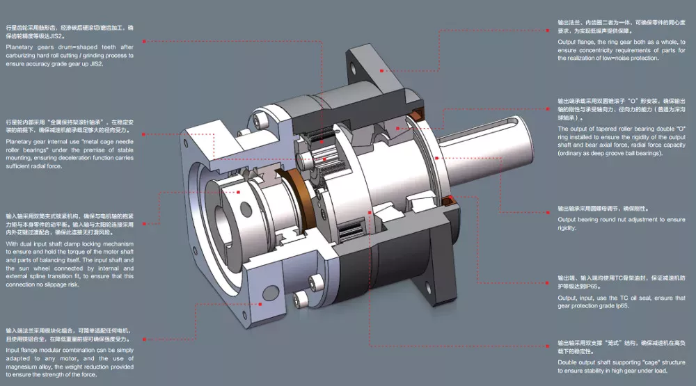
CAPK Series
The CZPT APK Series is a high precision, rotary flange style planetary gearbox. Its case hardened and ground gears are designed to provide excellent wear resistance, low backlash, and excellent precision. The CAPK Series offers high axial and moment load capacities in a compact housing. CZPT is the world leader in the production of planetary gearboxes. The CAPK Series features an array of high-quality, innovative features.
CZPT SMART Lubrication technology is used to keep the gears well-lubricated and reduce noise and vibration. The planetary gearbox’s 3-gear design is ideal for DIY CNC robotics. This series has a long history of quality, and CZPT uses only the best components. The CZPT 3:1 High Precision Planetary Gearbox is an excellent choice for CNC Robotics and other applications.
A multi-stage planetary gearbox combines individual ratios for a greater number of ratios. Additional planetary gears increase the transmittable torque. The direction of the output and drive shaft are always identical. The CAPK Series features a high-quality, durable construction. They are made from stainless steel and offer a long-term warranty. They are the best choice for industrial and commercial applications. While planetary gears are more expensive, they are highly efficient.
CFH Series
The Candy CFH Series planetary gearboxes offer the benefits of a modular design and a low backlash. They offer a variety of size options and excellent durability. This planetary gearbox is compact and wear resistant. The CFH Series planetary gearbox has a carburized, induction hardened gears and a rigid alloy steel housing. Its low backlash and precision make it an excellent choice for industrial applications.
The CFH Series planetary gearbox is a highly efficient, high-speed helical gear. The compact design of this gearbox results in high heat dissipation and low mass inertia. Planet carrier bearings experience significant lateral forces from the transmission of torque. As a result, radial and axial forces oppose each other. The result is that the torque is distributed over three gears, reducing noise, vibration, and wear.
The planetary gearbox has three main components: a sun gear (also known as the input gear), a ring gear, and two planet gears. These are connected by a carrier that rotates about a 45-degree clockwise axis. The CFH Series of gears is available in triple and double stages. They can also be used in electric motors. As a result, the CFH Series is highly versatile.
The CFH Series of planetary gearboxes can be found in all kinds of applications, including automotive transmissions. Their compact design and high-performance performance make them a popular choice for space-constrained applications. This gearbox has several benefits and is a great alternative to a conventional helical gearbox. These gearboxes are highly effective for reducing torque and speed, and are compact enough to fit in most applications.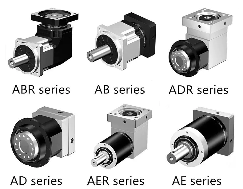
CZPT
If you need a high-quality planetary gearbox, the CZPT Planetary Series is the right choice. This Italian company designs and manufactures gearboxes in its San Polo d’Enza, Italy, facility with 11 branch offices and three production facilities. The company is attempting to replicate the success of the Italian Super Car industry, which has gained global recognition. The company provides a range of gearboxes for use in heavy industry, agriculture, offshore, aerial and marine work.
With over 40 years of experience, CZPT manufactures a wide range of high-quality gearboxes. From bevel-helical units to Helical units, wheel gears and negative brakes, the company has been manufacturing quality components for many industries. CZPT is a trusted Australian distributor of CZPT gear components. The company is dedicated to providing the best planetary gears for every industry.
If your CZPT Planetary gearbox is malfunctioning, you can have it repaired quickly and easily. The company uses quality materials and a variety of sizes and output ratios to cater to the most demanding applications. In addition, you can customize your gearbox to suit your specific needs. CZPT Planetary Gearboxes are highly versatile and customizable, offering infinite scalability.
editor by Dream 2024-04-26
China Professional Wire Twisting Machine Assembly Gp15A Traverse Unit Rolling Ring Drive
Product Description
Product Description
Wire twisting machine assembly GP15A traverse unit rolling ring drive
Manufacturer of automatic linear transmission gear with well-equipped testing facilities and strong technical force
| Type | GP15A |
| Shaft Diameter | 15 mm |
| Number of Rolling Rings | 3 Pieces |
| Maximum Thrust(N) | 100 N |
| Weight-Bearing(KG) | 10 kg |
| Maximum Pitch(mm) | 11 mm |
| Weight(KG) | 1.2 kg |
Product Parameters
Detailed Photos
ROTATION DIRECTION (CAN CHANGE)
Packaging & Shipping
|
Package Material
|
Wooden Box or Carton |
|
Package Detail
|
1piece or 5 pieces per carton package or wooden carton |
|
Delivery Way
|
Deliver the goods by express, like UPS, DHL, FedEx or by sea shipment or according to customer’s requirement |
Product Application
Rolling ring drive/ traverse unit device is mostly used in industry. Used in textile machine, wire spooling machine, traverse winding machine, wire winding machine, linear drive system, medical equipment, etc.
Different Type of Product
Rolling Ring Drive has GPA, GPB, CHINAMFG Series, It is widely used in wire,steel wire,electrical wire, cable, textile industry etc.
A Series : Rolling ring drives Type A Series just have 1 rolling ring linear drive box , which are divided into six types according to the diameter of the shafts.
B Series: Rolling ring drives Type B Series have One Rolling Ring linear drive with Xihu (West Lake) Dis. Rollers or Xihu (West Lake) Dis. Wheel , which are divided into 6 types according to the diameter of the shafts.
C Series : Rolling ring drives Type C Series have One Rolling Ring linear drive with accessories, such as shaft,guide roller,bearing block,steady bar,etc , which are divided into six types according to the diameter of the shafts.
FAQ
Q1. What is your terms of packing?
A: Generally, we pack our goods in carton boxes or wooden boxes.
Q2. What is your terms of payment?
A: T/T 100% paymeny in advance, or 30% as deposit, and 70% before delivery. We’ll show you the photos of the products and packages before you pay the balance.
Q3. What is your terms of delivery?
A: EXW, FOB, CFR, CIF, DDU.
Q4. How about your delivery time?
A: Generally, it will send this product within 3 or 5 days after receiving your payment. The specific delivery time depends on the items and the quantity of your order.
Q5. What is your sample policy?
A: We can supply the sample if we have ready parts in stock, but the customers have to pay the sample cost and the courier cost.
Q6. Do you test all your goods before delivery?
A: Yes, we have 100% test before delivery
Q7: How do you make our business long-term and good relationship?
A:1. We keep good quality and competitive price to ensure our customers benefit ;
2. We respect every customer as our friend and we sincerely do business and make friends with them, no matter where they come from.
/* January 22, 2571 19:08:37 */!function(){function s(e,r){var a,o={};try{e&&e.split(“,”).forEach(function(e,t){e&&(a=e.match(/(.*?):(.*)$/))&&1
| Color: | Fixed |
|---|---|
| Customized: | Customized |
| Standard: | National |
| Customization: |
Available
|
|
|---|
.shipping-cost-tm .tm-status-off{background: none;padding:0;color: #1470cc}
|
Shipping Cost:
Estimated freight per unit. |
about shipping cost and estimated delivery time. |
|---|
| Payment Method: |
|
|---|---|
|
Initial Payment Full Payment |
| Currency: | US$ |
|---|
| Return&refunds: | You can apply for a refund up to 30 days after receipt of the products. |
|---|
How do pitch drives contribute to the adaptability and versatility of adjustable systems in various settings?
Pitch drives play a crucial role in enhancing the adaptability and versatility of adjustable systems across various settings. These drives enable precise control over the pitch angles of adjustable components, allowing them to respond dynamically to changing operating conditions. Here’s a detailed explanation of how pitch drives contribute to the adaptability and versatility of adjustable systems:
- Optimized Performance: By adjusting the pitch angles of blades, propellers, or other adjustable components, pitch drives optimize the performance of adjustable systems. In applications such as wind turbines or marine propulsion systems, pitch drives enable the system to capture maximum energy from the wind or water currents. By adjusting the pitch angles based on real-time conditions, such as wind speed or load demand, pitch drives ensure that the system operates at its peak performance, maximizing energy conversion, and overall efficiency.
- Load Control and Mitigation: Pitch drives provide load control capabilities, allowing adjustable systems to manage and mitigate excessive loads. By adjusting the pitch angles, the systems can redistribute the loads on components, reducing stress concentrations and minimizing the risk of fatigue or failure. This load control capability is particularly valuable in applications where adjustable systems operate under varying and unpredictable load conditions, such as wind turbines experiencing gusty winds or marine systems encountering wave-induced loads.
- Dynamic Response: The ability of pitch drives to adjust pitch angles in real-time enables adjustable systems to have a dynamic response to changing operating conditions. For example, in wind turbines, pitch drives can respond to sudden changes in wind speed or direction, allowing the blades to maintain optimal aerodynamic performance and prevent excessive loads. This dynamic response capability enhances the adaptability of adjustable systems, enabling them to quickly adjust and optimize their operation in response to environmental changes.
- Power Regulation: Pitch drives contribute to the adaptability of adjustable systems by enabling power regulation. By adjusting the pitch angles, the systems can control the power output or torque generation. This is particularly useful in applications such as wind turbines, where pitch drives can regulate the rotational speed of the blades to match the desired power output or grid requirements. This power regulation capability enhances the versatility of adjustable systems by allowing them to operate efficiently across a wide range of power demands or grid conditions.
- Operational Flexibility: Adjustable systems equipped with pitch drives offer operational flexibility in various settings. The ability to adjust pitch angles allows these systems to adapt to different operating conditions, load profiles, or environmental factors. For example, in wind turbines, pitch drives enable the system to operate optimally in both low and high wind speeds, maximizing energy capture across a wide range of wind conditions. This operational flexibility makes adjustable systems with pitch drives suitable for diverse applications and settings.
- System Protection: Pitch drives contribute to the adaptability and versatility of adjustable systems by providing system protection features. In situations where excessive loads, extreme weather conditions, or potential hazards are detected, pitch drives can adjust the pitch angles to protect the system from damage or unsafe operating conditions. This proactive system protection capability enhances the adaptability and safety of adjustable systems, allowing them to operate reliably and withstand challenging conditions.
In summary, pitch drives significantly contribute to the adaptability and versatility of adjustable systems by optimizing performance, enabling load control and mitigation, providing dynamic response, regulating power, offering operational flexibility, and ensuring system protection. These capabilities make pitch drives essential components in various settings, ranging from renewable energy generation to marine propulsion, where the ability to adjust and optimize system parameters is critical for efficient and reliable operation.

Can pitch drives be customized for specific industries or machinery configurations?
Yes, pitch drives can be customized to meet the specific requirements of different industries or machinery configurations. Customization allows pitch drives to be tailored to the unique needs and constraints of a particular application, ensuring optimal performance, compatibility, and integration. Here’s a detailed explanation of how pitch drives can be customized for specific industries or machinery configurations:
1. Industry-specific Requirements: Different industries may have specific requirements that need to be considered when designing and customizing pitch drives. For example, the wind energy industry requires pitch drives for wind turbines that comply with industry standards and certifications. These standards may dictate factors such as load capacities, environmental durability, safety features, and communication protocols. Customization ensures that the pitch drives meet these industry-specific requirements.
2. Machinery Configuration: Machinery configurations can vary significantly across different applications. Customization allows pitch drives to be designed and adapted to fit specific machinery configurations, including physical dimensions, mounting options, and interface requirements. By customizing the pitch drives to the machinery configuration, optimal integration and performance can be achieved.
3. Power and Torque Requirements: The power and torque requirements of different machinery applications can vary. Customization allows pitch drives to be designed to provide the necessary force or torque output required for precise pitch adjustments. By considering the specific power and torque needs of the machinery, the customized pitch drives can deliver the required performance and control.
4. Control System Integration: Pitch drives can be customized to integrate seamlessly with the existing control systems of the machinery. This customization ensures compatibility and facilitates smooth communication and coordination between the pitch drives and other components or subsystems. By customizing the pitch drives for control system integration, precise and controlled pitch adjustments can be achieved within the overall machinery control architecture.
5. Environmental Considerations: Customization of pitch drives can take into account the specific environmental conditions in which the machinery operates. Factors such as temperature, humidity, dust, and vibration levels can impact the performance and durability of the pitch drives. By customizing the pitch drives to withstand and operate reliably under these environmental conditions, their suitability and longevity in specific industries can be enhanced.
6. Specialized Features: Customization allows for the incorporation of specialized features or functionalities to meet unique industry or application requirements. This could include features such as advanced control algorithms, communication protocols, remote monitoring capabilities, or specific safety mechanisms. By customizing pitch drives with these specialized features, they can be optimized for specific industries or machinery configurations.
It’s important to note that customization may involve collaboration between the pitch drive manufacturer and the machinery designer or end-user. Close communication and understanding of the specific needs and constraints of the industry or machinery configuration are crucial for successful customization.
In summary, pitch drives can be customized to accommodate the requirements of specific industries or machinery configurations. Customization ensures that the pitch drives are tailored to meet industry standards, machinery specifications, power and torque requirements, control system integration, environmental considerations, and any specialized features needed for optimal performance and compatibility.

What is a pitch drive, and how is it used in the context of machinery or systems?
A pitch drive refers to a mechanical or electromechanical component used in machinery or systems to control the pitch angle of a rotating object or component. It is commonly employed in applications where precise control over the angle of rotation is required. The pitch drive mechanism is designed to adjust and maintain the desired pitch angle of the rotating object, enabling smooth and controlled motion. Here’s a detailed explanation of the concept and usage of a pitch drive in the context of machinery or systems:
In various mechanical systems, especially those involving rotating components such as propellers, turbines, or rotor blades, the pitch angle plays a crucial role in determining the performance, efficiency, and functionality. The pitch angle refers to the angle between the rotating object’s longitudinal axis and its plane of rotation. By adjusting the pitch angle, the aerodynamic or hydrodynamic characteristics of the rotating component can be modified, resulting in changes to thrust, lift, or other performance parameters.
A pitch drive mechanism consists of various components, including motors, gears, linkages, and control systems. The specific design and configuration depend on the application requirements and the complexity of the system. The primary function of the pitch drive is to provide controlled rotation and adjustment of the pitch angle, allowing precise control over the output or performance of the rotating component.
The pitch drive is typically controlled by a control system that receives input signals or commands to adjust the pitch angle. The control signals can come from various sources, such as manual control inputs, automated control algorithms, or feedback from sensors or monitoring systems. The control system processes the input signals and actuates the pitch drive mechanism accordingly to achieve the desired pitch angle.
In the context of specific applications, here are some examples of how pitch drives are used:
- Aircraft Propellers: Pitch drives are commonly used in aircraft propellers to control the pitch angle of the propeller blades. By adjusting the pitch angle, the propeller’s performance characteristics can be optimized for various flight conditions, such as takeoff, climb, cruise, or descent. The pitch drive allows the pilot or automated control system to change the pitch angle to achieve the desired thrust and efficiency.
- Wind Turbines: Pitch drives are employed in wind turbines to control the pitch angle of the turbine blades. Wind conditions can vary, and by adjusting the pitch angle, the turbine can optimize its operation for maximum power generation or to protect the system during high wind or storm conditions. The pitch drive mechanism enables the wind turbine to adjust the pitch angle of each blade individually or collectively to maintain optimal performance.
- Marine Propulsion Systems: Pitch drives are utilized in marine propulsion systems, such as ship propellers or watercraft thrusters. By adjusting the pitch angle of the propeller blades, the propulsion system can optimize thrust, maneuverability, and efficiency. Pitch drives allow for dynamic control of the pitch angle, enabling vessels to adapt to changing operating conditions or specific maneuvering requirements.
- Industrial Machinery: In various industrial machinery applications, pitch drives can be employed to control the pitch angle of rotating components like fan blades, impellers, or mixing blades. By adjusting the pitch angle, the performance, efficiency, or flow characteristics of the machinery can be controlled or optimized, leading to improved process outcomes.
Overall, pitch drives play a vital role in machinery or systems where precise control over the pitch angle of rotating components is required. By enabling adjustments to the pitch angle, these drives allow for optimization of performance, efficiency, and functionality in a wide range of applications, including aircraft, wind turbines, marine propulsion systems, and industrial machinery.
editor by Dream 2024-04-26
China supplier Mount 180 Flange Servo Motor for Industrial Automation
Product Description
Product Description
Company Profile
FAQ
| Q:How to choose a multi-degree-of-freedom motion platform? A: First, clarify the type of platform needed (degrees of freedom, simulation platform, positioning platform, swing platform, vibration platform, etc.). Next, determine the platform’s payload, followed by size requirements, and finally, specify the platform’s attitude data. Q:What is the repeatability of a multi-degree-of-freedom motion platform? Q:What is the resolution of a multi-degree-of-freedom motion platform? Q:Does a multi-degree-of-freedom motion platform require maintenance? How to maintain it? Q:What is the maximum effective load that a multi-degree-of-freedom motion platform can handle? Q:What is the maximum angular position that a multi-degree-of-freedom motion platform can achieve? |
/* January 22, 2571 19:08:37 */!function(){function s(e,r){var a,o={};try{e&&e.split(“,”).forEach(function(e,t){e&&(a=e.match(/(.*?):(.*)$/))&&1
| Application: | Industrial |
|---|---|
| Speed: | High Speed |
| Number of Stator: | Single-Phase |
| Function: | Driving, Control |
| Certification: | ISO9001 |
| Motor: | Servo Motor |
| Customization: |
Available
|
|
|---|
How do electronic or computer-controlled components integrate with pitch drives in modern applications?
Electronic or computer-controlled components play a crucial role in the integration of pitch drives in modern applications. These components enable precise control, monitoring, and coordination of pitch adjustments, enhancing the performance, efficiency, and safety of adjustable systems. Here’s a detailed explanation of how electronic or computer-controlled components integrate with pitch drives in modern applications:
- Control Systems: Electronic control systems are used to regulate and coordinate the operation of pitch drives. These systems receive input signals, such as wind speed, power demand, or operator commands, and translate them into control signals that govern the pitch angle adjustments. The control systems monitor the system’s operating conditions and adjust the pitch drives accordingly to maintain optimal performance, efficiency, and safety.
- Sensors: Sensors are integrated with pitch drives to provide real-time feedback on various parameters. For example, wind turbines may incorporate wind speed sensors, blade position sensors, or load sensors to continuously monitor the environmental conditions and system response. The sensor data is fed into the control system, allowing it to make informed decisions regarding pitch adjustments. Sensors enable precise control and ensure that the pitch drives respond accurately to changing conditions.
- Actuators: Actuators are electronic or electromechanical devices that convert control signals from the control system into physical motion. In the context of pitch drives, actuators are responsible for adjusting the pitch angles of blades, propellers, or other adjustable components. The control system sends signals to the actuators, specifying the desired pitch angle, and the actuators actuate the pitch drives accordingly. Actuators enable precise and dynamic control over the pitch adjustments, contributing to the overall performance and efficiency of the adjustable systems.
- Communication and Networking: Electronic or computer-controlled components facilitate communication and networking capabilities in modern pitch drive applications. They enable data exchange between the control system, sensors, actuators, and other system components. This communication allows for coordinated operation, data logging, remote monitoring, and integration with higher-level control systems or supervisory systems. Networking technologies, such as Ethernet, CAN bus, or wireless protocols, facilitate efficient data transmission and system integration.
- Embedded Systems and Microcontrollers: Embedded systems and microcontrollers are often employed in modern pitch drive applications. These compact and powerful computing devices are dedicated to performing specific control and monitoring tasks. They execute control algorithms, handle sensor inputs, and generate actuator outputs in real-time. Embedded systems and microcontrollers provide the computational power and responsiveness required for precise and reliable control of pitch drives.
- Data Analysis and Optimization: Electronic or computer-controlled components enable data analysis and optimization techniques for pitch drives. They can collect and process data from various sensors and feedback loops to identify performance trends, detect anomalies, and optimize control strategies. This data-driven approach allows for continuous improvement of system performance, energy efficiency, and predictive maintenance.
The integration of electronic or computer-controlled components with pitch drives in modern applications enables advanced functionality, flexibility, and performance optimization. By integrating control systems, sensors, actuators, communication capabilities, embedded systems, and data analysis techniques, adjustable systems can achieve precise control, adaptive response, and efficient operation, resulting in enhanced overall performance and functionality.
What maintenance practices are recommended for pitch drives to ensure optimal functionality?
Maintenance practices play a crucial role in ensuring the optimal functionality and longevity of pitch drives. Regular maintenance helps identify and address potential issues, minimize downtime, and maximize the performance and reliability of pitch drives. Here are some recommended maintenance practices for pitch drives:
- Inspection and Cleaning: Regular visual inspections should be conducted to identify any signs of wear, damage, or contamination. The pitch drives should be cleaned to remove dirt, debris, or environmental contaminants that can affect their performance. This includes cleaning the external surfaces as well as inspecting internal components, such as bearings, seals, and electrical connections.
- Lubrication: Proper lubrication is essential for the smooth operation of pitch drives. The lubrication schedule recommended by the manufacturer should be followed, and appropriate lubricants should be used. This helps reduce friction, minimize wear, and prolong the life of moving parts, such as gears, bearings, and sliding surfaces.
- Torque and Tension Checks: Regular checks should be performed to ensure that the fasteners, bolts, and connections in the pitch drive system are properly torqued and tightened. Any loose or damaged fasteners should be addressed promptly to prevent potential issues, such as misalignment or component failure.
- Electrical System Maintenance: If the pitch drive incorporates electrical components, regular inspections and testing of the electrical system should be conducted. This includes checking the wiring integrity, insulation, and connections, as well as verifying the performance of sensors, actuators, and control systems. Any abnormalities or malfunctions should be addressed promptly to maintain the electrical functionality of the pitch drives.
- Alignment and Calibration: Periodic alignment and calibration of the pitch drives are important to ensure accurate and precise pitch adjustments. Misalignment can lead to improper load distribution, increased wear, or reduced performance. The alignment and calibration procedures recommended by the manufacturer should be followed to maintain the optimal functionality of the pitch drives.
- Condition Monitoring: Implementing condition monitoring techniques, such as vibration analysis, thermal imaging, or oil analysis, can help detect early signs of potential issues in pitch drives. By monitoring key parameters and analyzing trends, maintenance personnel can identify abnormal behavior or degradation in components, allowing for proactive maintenance actions to be taken before major failures occur.
- Record Keeping and Documentation: Maintaining detailed records of maintenance activities, inspections, repairs, and component replacements is essential. This documentation helps track the maintenance history, identify recurring issues, and ensure that maintenance tasks are performed at appropriate intervals. It also aids in warranty claims, troubleshooting, and future maintenance planning.
It’s important to note that maintenance practices may vary depending on the specific type of pitch drive, manufacturer’s recommendations, and operating conditions. Following the manufacturer’s guidelines, consulting maintenance manuals, and seeking professional assistance when needed are essential for implementing the most appropriate maintenance practices for the specific pitch drive system.
By implementing regular maintenance practices, pitch drives can operate optimally, minimize the risk of unexpected failures, and contribute to the overall efficiency, performance, and reliability of the machinery or systems they are a part of.
What is a pitch drive, and how is it used in the context of machinery or systems?
A pitch drive refers to a mechanical or electromechanical component used in machinery or systems to control the pitch angle of a rotating object or component. It is commonly employed in applications where precise control over the angle of rotation is required. The pitch drive mechanism is designed to adjust and maintain the desired pitch angle of the rotating object, enabling smooth and controlled motion. Here’s a detailed explanation of the concept and usage of a pitch drive in the context of machinery or systems:
In various mechanical systems, especially those involving rotating components such as propellers, turbines, or rotor blades, the pitch angle plays a crucial role in determining the performance, efficiency, and functionality. The pitch angle refers to the angle between the rotating object’s longitudinal axis and its plane of rotation. By adjusting the pitch angle, the aerodynamic or hydrodynamic characteristics of the rotating component can be modified, resulting in changes to thrust, lift, or other performance parameters.
A pitch drive mechanism consists of various components, including motors, gears, linkages, and control systems. The specific design and configuration depend on the application requirements and the complexity of the system. The primary function of the pitch drive is to provide controlled rotation and adjustment of the pitch angle, allowing precise control over the output or performance of the rotating component.
The pitch drive is typically controlled by a control system that receives input signals or commands to adjust the pitch angle. The control signals can come from various sources, such as manual control inputs, automated control algorithms, or feedback from sensors or monitoring systems. The control system processes the input signals and actuates the pitch drive mechanism accordingly to achieve the desired pitch angle.
In the context of specific applications, here are some examples of how pitch drives are used:
- Aircraft Propellers: Pitch drives are commonly used in aircraft propellers to control the pitch angle of the propeller blades. By adjusting the pitch angle, the propeller’s performance characteristics can be optimized for various flight conditions, such as takeoff, climb, cruise, or descent. The pitch drive allows the pilot or automated control system to change the pitch angle to achieve the desired thrust and efficiency.
- Wind Turbines: Pitch drives are employed in wind turbines to control the pitch angle of the turbine blades. Wind conditions can vary, and by adjusting the pitch angle, the turbine can optimize its operation for maximum power generation or to protect the system during high wind or storm conditions. The pitch drive mechanism enables the wind turbine to adjust the pitch angle of each blade individually or collectively to maintain optimal performance.
- Marine Propulsion Systems: Pitch drives are utilized in marine propulsion systems, such as ship propellers or watercraft thrusters. By adjusting the pitch angle of the propeller blades, the propulsion system can optimize thrust, maneuverability, and efficiency. Pitch drives allow for dynamic control of the pitch angle, enabling vessels to adapt to changing operating conditions or specific maneuvering requirements.
- Industrial Machinery: In various industrial machinery applications, pitch drives can be employed to control the pitch angle of rotating components like fan blades, impellers, or mixing blades. By adjusting the pitch angle, the performance, efficiency, or flow characteristics of the machinery can be controlled or optimized, leading to improved process outcomes.
Overall, pitch drives play a vital role in machinery or systems where precise control over the pitch angle of rotating components is required. By enabling adjustments to the pitch angle, these drives allow for optimization of performance, efficiency, and functionality in a wide range of applications, including aircraft, wind turbines, marine propulsion systems, and industrial machinery.
editor by Dream 2024-04-26
China OEM Wire Winder Machine Traverse Roll System Gp60c Rolling Ring Drive
Product Description
Product Description
Wire Winder Machine Traverse Roll System gp60c Rolling Ring Drive
Manufacturer of automatic linear transmission gear with well-equipped testing facilities and strong technical force
| Type | GP60C |
| Shaft Diameter | 60 mm |
| Number of Rolling Rings | 3 Pieces |
| Maximum Thrust(N) | 1000 N |
| Weight-Bearing(KG) | 100 kg |
| Maximum Pitch(mm) | 48 mm |
| Weight(KG) | 78 kg |
| Linear Xihu (West Lake) Dis. Length | Standard length 1000mm or Customized length |
Product Parameters
Detailed Photos
ROTATION DIRECTION (CAN CHANGE)
Packaging & Shipping
|
Package Material
|
Wooden Box or Carton |
|
Package Detail
|
1piece or 5 pieces per carton package or wooden carton |
|
Delivery Way
|
Deliver the goods by express, like UPS, DHL, FedEx or by sea shipment or according to customer’s requirement |
Product Application
Rolling ring drive/ traverse unit device is mostly used in industry. Used in textile machine, wire spooling machine, traverse winding machine, wire winding machine, linear drive system, medical equipment, etc.
Different Type of Product
Rolling Ring Drive has GPA, GPB, CHINAMFG Series, It is widely used in wire,steel wire,electrical wire, cable, textile industry etc.
A Series : Rolling ring drives Type A Series just have 1 rolling ring linear drive box , which are divided into six types according to the diameter of the shafts.
B Series: Rolling ring drives Type B Series have One Rolling Ring linear drive with Xihu (West Lake) Dis. Rollers or Xihu (West Lake) Dis. Wheel , which are divided into 6 types according to the diameter of the shafts.
C Series : Rolling ring drives Type C Series have One Rolling Ring linear drive with accessories, such as shaft,guide roller,bearing block,steady bar,etc , which are divided into six types according to the diameter of the shafts.
FAQ
Q1. What is your terms of packing?
A: Generally, we pack our goods in carton boxes or wooden boxes.
Q2. What is your terms of payment?
A: T/T 100% paymeny in advance, or 30% as deposit, and 70% before delivery. We’ll show you the photos of the products and packages before you pay the balance.
Q3. What is your terms of delivery?
A: EXW, FOB, CFR, CIF, DDU.
Q4. How about your delivery time?
A: Generally, it will send this product within 3 or 5 days after receiving your payment. The specific delivery time depends on the items and the quantity of your order.
Q5. What is your sample policy?
A: We can supply the sample if we have ready parts in stock, but the customers have to pay the sample cost and the courier cost.
Q6. Do you test all your goods before delivery?
A: Yes, we have 100% test before delivery
Q7: How do you make our business long-term and good relationship?
A:1. We keep good quality and competitive price to ensure our customers benefit ;
2. We respect every customer as our friend and we sincerely do business and make friends with them, no matter where they come from.
/* January 22, 2571 19:08:37 */!function(){function s(e,r){var a,o={};try{e&&e.split(“,”).forEach(function(e,t){e&&(a=e.match(/(.*?):(.*)$/))&&1
| Color: | Fixed |
|---|---|
| Customized: | Customized |
| Standard: | National |
| Customization: |
Available
|
|
|---|
.shipping-cost-tm .tm-status-off{background: none;padding:0;color: #1470cc}
|
Shipping Cost:
Estimated freight per unit. |
about shipping cost and estimated delivery time. |
|---|
| Payment Method: |
|
|---|---|
|
Initial Payment Full Payment |
| Currency: | US$ |
|---|
| Return&refunds: | You can apply for a refund up to 30 days after receipt of the products. |
|---|
How does the choice of pitch drives affect the overall performance and reliability of adjustable systems?
The choice of pitch drives has a significant impact on the overall performance and reliability of adjustable systems. Here’s a detailed explanation of how the choice of pitch drives affects these aspects:
- Performance:
The performance of adjustable systems, such as wind turbines or rotor blades, depends on the effectiveness and responsiveness of the pitch control mechanism. The choice of pitch drives directly influences the system’s ability to adjust the pitch angles accurately, quickly, and precisely. Several factors contribute to the performance impact:
- Speed and Responsiveness: The speed at which pitch drives can adjust the pitch angles affects the system’s ability to optimize performance in changing wind conditions. High-performance pitch drives with fast response times enable quicker and more precise adjustments, allowing the system to capture more energy from the wind and maintain optimal operating conditions.
- Control Accuracy: The accuracy of pitch angle control is crucial for maintaining the desired power output, load distribution, and overall system stability. The choice of pitch drives with precise control mechanisms ensures that the adjustable components accurately follow the control commands, minimizing deviations from the desired pitch angles and maximizing energy capture.
- Dynamic Performance: Adjustable systems often experience dynamic loads and varying wind conditions. The choice of pitch drives with robust dynamic performance characteristics, such as high torque capacity and low inertia, allows the system to effectively respond to dynamic loads, maintain stability, and optimize power generation.
- Reliability:
The reliability of adjustable systems is heavily influenced by the choice of pitch drives. The reliability aspect encompasses the system’s ability to operate consistently, withstand environmental conditions, and minimize the risk of failures or malfunctions. The choice of pitch drives impacts reliability in the following ways:
- Durability and Longevity: High-quality pitch drives designed for industrial applications provide durability and extended service life. They can withstand the operational stresses, environmental conditions, and mechanical loads associated with adjustable systems, reducing the likelihood of premature failures and the need for frequent replacements.
- Mechanical Integrity: The mechanical integrity of pitch drives, including the gears, bearings, and other moving components, is crucial for reliable operation. Choosing pitch drives from reputable manufacturers with a track record of reliable products ensures the use of robust and well-engineered components that can withstand continuous operation and minimize the risk of mechanical failures.
- Maintenance and Serviceability: The choice of pitch drives can influence the ease of maintenance and serviceability of adjustable systems. Well-designed pitch drives with accessible maintenance points, clear documentation, and available spare parts facilitate routine maintenance tasks, inspections, and repairs, reducing downtime and enhancing overall system reliability.
- Environmental Considerations: Adjustable systems often operate in challenging environmental conditions, such as high winds, temperature variations, and exposure to dust, moisture, or corrosive elements. The choice of pitch drives that are specifically designed and tested for such environments ensures resistance to environmental stresses, enhancing the reliability and longevity of the system.
In summary, the choice of pitch drives significantly affects the performance and reliability of adjustable systems. The selection of pitch drives with high-speed responsiveness, precise control accuracy, and robust dynamic performance optimizes the system’s performance in varying wind conditions. Additionally, choosing pitch drives with durability, mechanical integrity, ease of maintenance, and environmental suitability enhances the overall reliability of the system by minimizing the risk of failures, extending service life, and facilitating maintenance activities.
Can you provide examples of products or machinery that commonly use pitch drives?
There are several products and machinery in various industries that commonly use pitch drives for precise and controlled pitch adjustments. These pitch drives play a crucial role in optimizing performance, efficiency, and safety. Here are some examples of products or machinery that commonly use pitch drives:
- Wind Turbines: Pitch drives are extensively used in wind turbines to adjust the pitch angle of the turbine blades. By changing the pitch angle, the rotor’s aerodynamic characteristics can be optimized to capture the maximum amount of wind energy. Pitch drives allow wind turbine operators to control the rotational speed, regulate power output, and ensure safe operation under varying wind conditions.
- Helicopters: Helicopters rely on pitch drives to adjust the pitch angle of the rotor blades. Pitch adjustments enable the helicopter to generate lift, control its altitude, and maneuver in different directions. By changing the pitch angle of individual rotor blades, pitch drives allow for precise control of the helicopter’s flight characteristics, including stability, responsiveness, and load distribution.
- Marine Propulsion Systems: Pitch drives are commonly used in marine propulsion systems, such as controllable pitch propellers (CPP) or azimuth thrusters. Pitch adjustments in marine propulsion systems allow vessels to optimize their propulsion efficiency, maneuverability, and dynamic positioning capabilities. By changing the pitch angle of the propeller blades, pitch drives enable vessels to adapt to varying operating conditions, such as different speeds, sea states, or maneuvering requirements.
- Aircraft Propellers: Aircraft with variable-pitch propellers utilize pitch drives to adjust the pitch angle of the propeller blades. By changing the propeller blade pitch, the aircraft can optimize performance during different phases of flight, such as takeoff, climb, cruise, or descent. Pitch drives allow for efficient power management, improved thrust-to-weight ratio, and enhanced control over the aircraft’s speed and climb rate.
- Industrial Fans: Industrial fans, such as those used in HVAC systems or cooling applications, often incorporate pitch drives for blade angle adjustment. By adjusting the pitch angle of the fan blades, pitch drives enable precise control of airflow, pressure, and energy consumption. This control allows for optimized cooling performance, improved ventilation, and energy efficiency in industrial and commercial settings.
- Propulsion Systems for Unmanned Aerial Vehicles (UAVs): UAVs, or drones, commonly utilize pitch drives in their propulsion systems. By adjusting the pitch angle of the propellers, pitch drives enable UAVs to control their altitude, stability, and maneuverability. This control is crucial for various applications, including aerial photography, surveillance, package delivery, and scientific research.
These examples highlight the diverse range of products and machinery that commonly use pitch drives for precise and controlled pitch adjustments. Other industries, such as the automotive, robotics, and power generation sectors, may also employ pitch drives in specific applications where pitch angle control is essential for optimized performance and operational safety.
How does the design of a pitch drive contribute to efficient adjustment or movement?
The design of a pitch drive plays a crucial role in enabling efficient adjustment or movement of the pitch angle in machinery or systems. The design factors of a pitch drive are carefully considered to ensure precise control, reliability, and optimal performance. Here’s a detailed explanation of how the design of a pitch drive contributes to efficient adjustment or movement:
The design considerations of a pitch drive include the following aspects:
- Mechanical Structure: The mechanical structure of a pitch drive is designed to provide the necessary strength, rigidity, and durability to withstand the operational forces and loads. It ensures that the pitch drive can effectively transmit and control the required torque and movement to adjust the pitch angle. The design considers factors such as material selection, component dimensions, and overall structural integrity to ensure efficient adjustment without compromising the system’s reliability.
- Gearing System: Pitch drives often incorporate gearing systems to transmit and amplify the rotational motion. The design of the gearing system is crucial for efficient adjustment or movement. It ensures precise torque transmission, minimal backlash, and smooth operation. The gear ratio and gear quality are carefully chosen to achieve the desired pitch angle adjustment range and accuracy. The design of the gears also considers factors such as noise reduction, lubrication, and maintenance requirements.
- Actuation Mechanism: The actuation mechanism of a pitch drive depends on the specific application and requirements. It can involve various technologies such as hydraulic, pneumatic, or electric actuators. The design of the actuation mechanism focuses on providing precise and responsive control over the pitch angle adjustment. Factors such as actuator speed, force or torque output, and control system integration are considered to ensure efficient adjustment or movement.
- Control System Integration: The design of a pitch drive includes the integration of a control system that governs the pitch angle adjustment. The control system receives input signals or commands and translates them into appropriate actuation signals for the pitch drive mechanism. The design of the control system ensures accurate and responsive control, taking into account factors such as sensor feedback, signal processing, and control algorithms. Efficient control system design facilitates precise and dynamic adjustment of the pitch angle in real-time.
The design features and considerations of a pitch drive contribute to efficient adjustment or movement in several ways:
- High Precision: The design ensures precise control over the pitch angle, allowing for fine adjustments and accurate positioning. This precision is crucial in applications where small changes in the pitch angle can significantly impact performance, efficiency, or safety.
- Smooth Operation: The design minimizes friction, backlash, and mechanical vibrations, resulting in smooth and consistent movement during pitch angle adjustment. Smooth operation reduces wear and tear, enhances system reliability, and improves overall performance.
- Speed and Responsiveness: The design factors in the actuation mechanism and control system to enable fast and responsive pitch angle adjustments. This is particularly important in applications where rapid changes in the pitch angle are required to adapt to dynamic operating conditions.
- Reliability: The design ensures the pitch drive’s structural integrity, component durability, and system reliability. This contributes to long-term operation without significant maintenance or downtime, enhancing the efficiency and productivity of the machinery or system.
- Safety: The design incorporates safety features and mechanisms to prevent unintended or excessive pitch angle adjustments. Safety considerations may include limit switches, emergency stop controls, or redundant systems to ensure safe operation and protect against potential hazards.
Overall, the design of a pitch drive is carefully engineered to provide efficient adjustment or movement of the pitch angle. By considering mechanical structure, gearing systems, actuation mechanisms, and control system integration, the design aims to achieve precise control, reliability, and optimal performance in machinery or systems that rely on pitch angle adjustment.
editor by Dream 2024-04-26